2 installing the encapsulator b-395 pro, Installing the encapsulator b-395 pro – BUCHI Encapsulator B-395 Pro User Manual
Page 20
5 Putting into operation
20
B-395 Pro
Operation Manual, Version C
5 .2
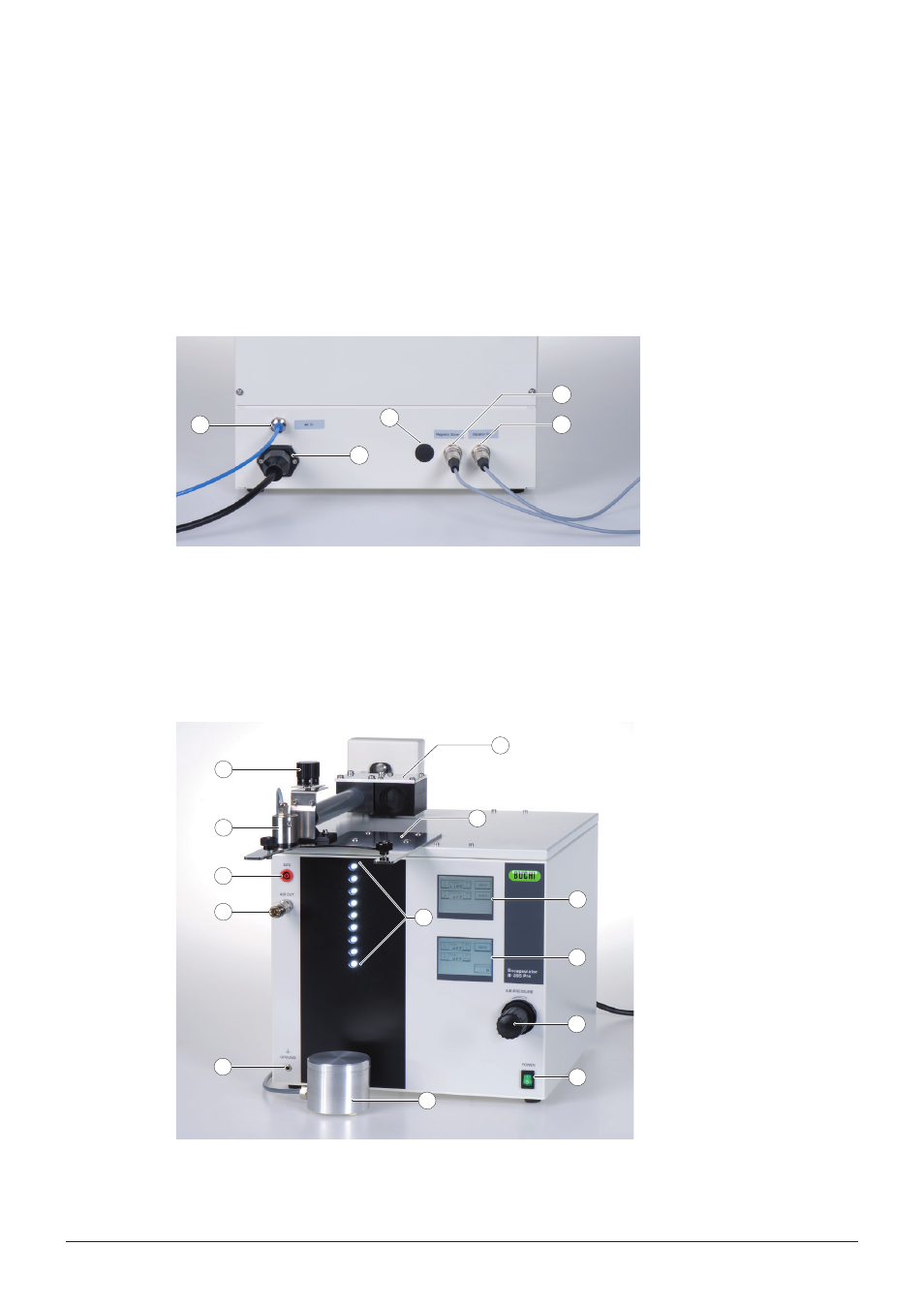
Installing the Encapsulator B-395 Pro
Place the instrument on the lab bench with convenient access to an AC electrical outlet and to
compressed air. Place the instrument in a way that disconnection of the electric supply plug is
possible at all times.
Installation of the magnetic stirrer, vibration unit and grounding wire
Connect the magnetic stirrer, the vibration unit and the grounding wire as shown in figure 5-1 and 5-2.
3
4
1
2
5
a Air inlet (blue tube 2.6×4.0 mm)
Electric supply socket with inte-
grated fuse
Optional socket
Socket for magnetic stirrer
Socket for vibration unit
Figure 5-1: Rear view of the control unit
All controlling systems for bead production are incorporated in the control unit. Vibration frequency,
pump speed, light intensity, electrostatic dispersion and magnetic stirrer speed are controlled on the
two touch screens. Air pressure is regulated with the pressure regulating valve. The integrated strobo-
scope lamp allows real time jet breakup control. The vibration unit is attached to the control unit on the
rear panel by a wire. The reaction vessel is attached to the reactor holder with two screws.
9
11
1
2
3
10
12
6
5
4
8
7
13
a Syringe pump
Reactor holder
Vibration unit
Upper touch screen (vibration
frequency & electrode)
Lower touch screen (syringe
pump, magnetic stirrer control &
pressure indication)
Pressure regulating valve
Stroboscope lamp
Mains switch
Magnetic stirrer
Air outlet
EDU (Voltage outlet)
Plug for grounding wire
LIquid flow regulating valve
Figure 5-2: Front view of the control unit