Panasonic AG-DP800HP User Manual
Page 73
Attention! The text in this document has been recognized automatically. To view the original document, you can use the "Original mode".
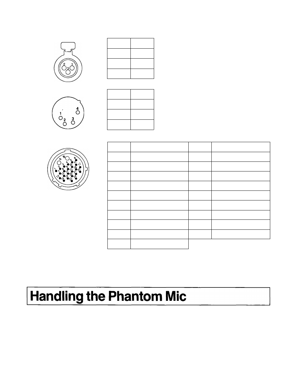
Audio input connector (XLR-3P)
External DC input connector (XLR-4P)
Pin No.
Signal
1
GND
2
HOT
3
COLD
Pin No.
Signal
1
GND
' 2,3
4
+ 12 V
26P VTR connector
Pin No.
Signal
Pin No.
Signal
1
COMPOSITE VIDEO
11
CAMERA MIC GND
2
COMPOSITE VIDEO GND
12
VTR START/STOP
3
YGND
15
REC TALLYWARNING
4
Y
16
5P DATA
5
R'Y
21
5P CLOCK
6
R-YGND
23
CTL PULSE
7
B-Y
24
5 P + 5 V
8
B-YGND
A
+ 12V
9
CAMERA MIC (H)
B
GND
10
CAMERA MIC (C)
Note;
When connecting the 26 pin VTR connector and the AU-55H,
set SW2 (component input level select switch) on the JACK
board of the AU-55H to the “S" side.
This camera recorder is designed to enable a phantom mic to be used as the unit's microphone (CH1/CH2). It can be selected on
menu item “AUDIO” in the viewfinder. For further details, refer to “How to set the menu items” (page 69).
[The phantom power supply is set to +48 V. Before shipment from the manufacturing plant, the camera recorder was set for
using the regular microphone (phantom power OFF).]
73