BendixKing SG 465 System EFS 40/50 User Manual
Page 87
MFD Operation
o
Configuration option number
one will slave the MFD to the #1
EHSI. The NAV push button will
cause the MFD to display either
the same NAV sensor as dis-
played on the EHSI or the LNAV.
When this configuration is select-
ed the 1-2 push button allows
selection between the on s i d e
and off side sensors. Once a
side is selected, that side will
remain the selected side until the
1-2 button is pressed again. This
allows the pilot the ability to
select the off side sensor to pro-
vide himself a constant visual
cross comparison.
o
Configuration option number
two enables the NAV button to
function identical to, but indepen-
dent of, the one on the ED 4 6 1 ,
C P 467 or CP 468. When this
configuration option is selected
the pilot can select any available
nav sensor for display on the
MFD independent of what is dis-
played on the EHSI.
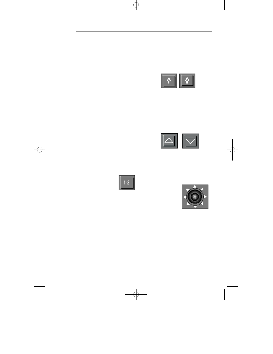
1-2 BUTTON
If NAV push button configuration
option number one is selected,
where the MFD is slaved to the
EHSI, the 1-2 push button allows
the pilot to select between on
side and off side NAV sensors.
Unlike the 1-2 push button on the
EHSI control panel, it selects
which side will be displayed until
pushed again. A press of the
NAV push button will not cause a
selected off side sensor to cycle
back to an on side sensor as it
does on the EHSI.
If NAV push button configuration
option number two is selected,
the 1-2 button functions identical
to, but independent of, the one on
the ED 461, CP 467 or CP 4 6 8 .
BEARING #1 & #2 BUTTON
Will function identical to, but inde-
pendent of, the one on the ED
461, CP 467 or CP 468.
Refer to section 2.1 EHSI OPER-
ATION for detail information.
RANGE UP/DOWN BUTTON
Will function identical to, but inde-
pendent of, the one on the ED
461, CP 467 or CP 4 6 8 .
Refer to section 2.1 EHSI OPER-
ATION for detail information.
JOYSTICK
w
W A Y P O I N T
E N T R Y
O P E R A T I O N
When the joystick is interfaced to
an EFS 40/50 system, it can be
used to generate and move sin-
gle waypoint on the display unit.
These waypoints can then be
entered into the KNS 81, KNS
660, KLN 88, KLN 90, or any
other LNAV using an appropriate
GAMA 429 interface. The KNS
2.4.3
Issued 8/10
SW 04/05/06/07/08/09/10/11/12/13/14/15/16
Section 2.4mp 9/8/10 7:49 PM Page 2.4.3