Installation guidelines, Ludlow – Waterworks Ludlow Floor Mounted Exposed Tub Filler with Handshower and Metal Lever Handles User Manual
Page 3
LUDLOW
Exposed Floor Mounted Tub Filler With Handshower
INSTALLATION GUIDELINES
Page 3 of 3
7.18.2014
These guidelines have been prepared for the professional contractor to aid in the installation of:
LUDLOW EXPOSED FLOOR MOUNTED TUB FILLER WITH HANDSHOWER WITH METAL CROSS
HANDLES (STYLE# LDXT60) & METAL LEVER HANDLES (STYLE# LDXT70)
All dimensions are based on original specification and are subject to change and variation.
Please consult your Design Associate for current specifications.
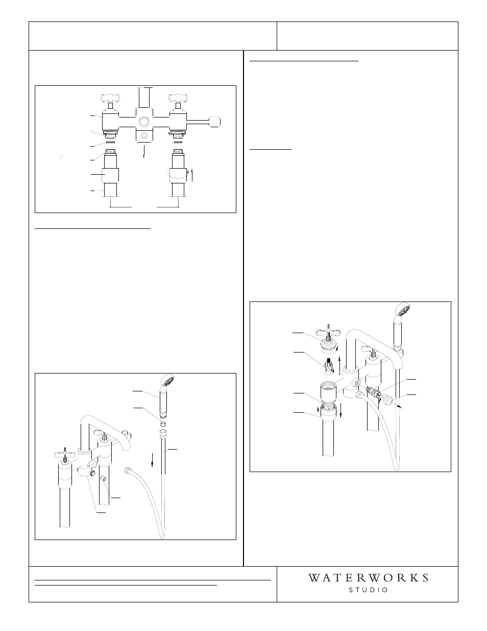
19. Slide the BOTTOM CAP back up the leg and thread
to TUB FILLER BODY to complete this install.
Figure 6
8"
[203mm]
TUB FILLER
BODY
UNION
CONNECTION
LEG
ASSEMBLY
BOTTOM CAP
3
4
" SWEAT
ADAPTER
RED FIBER
WASHER
HANDSHOWER INSTALLATION:
¾ See Figure 7. for Steps 20 & 21.
20. Attach the conical end of HANDSHOWER HOSE to
the HANDSHOWER.
21. Connect the other end of the HANDSHOWER HOSE
to the HANDSHOWER OUTLET. Place the
handshower on the HOOK. Note: The
HANDSHOWER OUTLET can swivel to re-position
the outlet to the desired orientation.
¾ Note: The FLOW REGULATING CHECK VALVE is
located in the inlet of the HANDSHOWER and the
CHECK VALVE is located in the outlet of the
HANDSHOWER OUTLET.
Figure 7
HANDSHOWER
FLOW
REGULATING
CHECK VALVE
HANDSHOWER
HOSE
HANDSHOWER
OUTLET
CHECK
VALVE
INSPECT THE INSTALLATION:
22. Turn on the supplies then open the hot and cold
valves to flush out any debris in the supply lines
before diverting to the handshower. To divert to the
handshower turn the diverter lever handle, which is
the center handle.
23. Carefully inspect all connections for leaks and check
for proper operation.
SERVICING:
¾ See Figure 8. for Steps 24-26.
¾ Service stops should be turned off prior to servicing.
¾ See Service Parts Document for parts ordering.
24. If the CARTRIDGES need servicing, the HANDLE
ASSEMBLY can be unthreaded from the BODY to
access them.
25. If entire BODY needs to be replaced, unthread
BOTTOM CAPS and slide them down the legs to
access UNION CONNECTIONS.
26. To service the DIVERTER, unthread the DIVERTER
KNOB and remove DIVERTER.
Figure 8
HANDLE
ASSEMBLY
CARTRIDGE
BOTTOM CAP
UNION NUT
DIVERTER
DIVERTER
KNOB
¾ If further assistance is required, please contact
Product Support at 1-800-927-2120 (9am-6pm EST).
¾ See service part document for parts ordering,
available on WATERWORKS.COM.