Installation guidelines, Ludlow, Exposed floor mounted tub filler with handshower – Waterworks Ludlow Floor Mounted Exposed Tub Filler with Handshower and Metal Lever Handles User Manual
Page 2
LUDLOW
Exposed Floor Mounted Tub Filler With Handshower
INSTALLATION GUIDELINES
Page 2 of 3
7.18.2014
These guidelines have been prepared for the professional contractor to aid in the installation of:
LUDLOW EXPOSED FLOOR MOUNTED TUB FILLER WITH HANDSHOWER WITH METAL CROSS
HANDLES (STYLE# LDXT60) & METAL LEVER HANDLES (STYLE# LDXT70)
All dimensions are based on original specification and are subject to change and variation.
Please consult your Design Associate for current specifications.
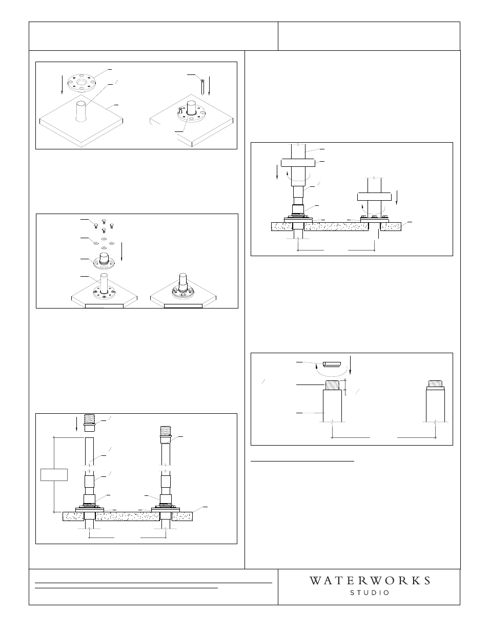
Figure 1
FINISHED
FLOOR
3
4
" COPPER
SUPPLY LINE
FLOOR
FLANGE
SOLDER
EDGE
FLOOR
SCREW
¾ See Figure 2 for Steps 9 & 10.
9. Slide LEG FLANGE over COPPER PIPE. Attach LEG
FLANGE to FLOOR FLANGE using FLANGE BOLTS
and METAL WASHERS.
Figure 2
LEG
FLANGE
METAL
WASHER
FLANGE
BOLTS
COPPER
PIPE
¾ See Figure 3 for Steps 10 & 11.
10. Extend the SUPPLY LINES and cut them to a height
of 27" (686mm) above the finished floor. Make sure
the cuts are flush and level.
11. Slide the 3/4" SWEAT ADAPTER onto the top of the
SUPPLY LINES and sweat them to the COPPER
PIPE. After soldering the adapters make sure they
are flush and level with each other.
Figure 3
27"
[686mm]
8"
[203mm]
3
4
" COPPER
SUPPLY LINE
[NOT SUPPLIED]
FLOOR
FLANGE
3
4
" COUPLER
[NOT SUPPLIED]
3
4
" SWEAT
ADAPTER
FINISHED
FLOOR
SOLDER
CONNECTION
LEG FLANGE
¾ See Figure 4 for Steps 12 - 14.
12. Slide LEG over SUPPLY PIPE & LEG FLANGE,
making sure the ESCUTCHEON is on the leg.
13. Thread the LEG onto the LEG FLANGE to secure leg.
14. Slide the ESCUTCHEONS back down the LEGS to
cover the floor mounting parts.
Figure 4
8"
[203mm]
FINISHED
FLOOR
LEG
ESCUTCHEON
FLOOR
FLANGE
3
4
" COUPLER
[NOT SUPPLIED]
LEG FLANGE
¾ See Figure 5 for Step 15.
¾ With the legs positioned over the copper supply
lines, the sweat adapter should be protruding 3/4"
past the leg assembly.
15. Thread the STABILIZING COLLAR onto 3/4" SWEAT
ADAPTER and tighten to secure LEG ASSEMBLY.
Note: Make sure the collar is fully seated into leg.
Figure 5
8"
[203mm]
STABILIZING
COLLAR
LEG
ASSEMBLY
3
4
"
[19mm]
3
4
" SWEAT
ADAPTER
TUB FILLER INSTALLATION:
¾ See Figure 6 for Steps 16 - 19.
16. Rotate the spout so that it is facing forwards and
then tighten the set screw.
17. Remove the BOTTOM CAP from the TUB FILLER
BODY and slide it down the LEG ASSEMBLY.
18. Position the TUB FILLER BODY over the secure LEG
ASSEMBLIES and tighten using UNION
CONNECTION nuts, making sure the RED FIBER
WASHER is in each union nut.