Waterworks Highgate Volume Control Valve Trim with White Porcelain Lever Handle User Manual
Installation guidelines
HIGHGATE
Volume Control Valve Trim
INSTALLATION GUIDELINES
Page 1 of 3
6.6.2012
These guidelines have been prepared for the professional contractor to aid in the installation of:
HIGHGATE VOLUME CONTROL VALVE TRIM WITH METAL CROSS HANDLE (STYLE# HGVC40) &
PORCELAIN LEVER HANDLE (STYLE# HGVC50)
All dimensions are based on original specification and are subject to change and variation.
Please consult your Design Associate for current specifications.
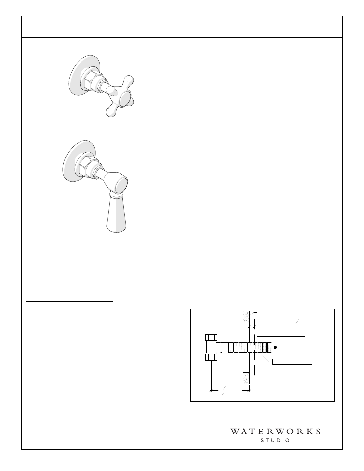
Metal Cross Handle
Style No. HGVC40
White Porcelain Lever Handle
Style No. HGVC50
SPECIFICATIONS:
Volume Control Valve Rough-in Depth:
GUVC18R (GUSV18R) or GUVC19R (GUSV19R):
3-1/4" MIN - 4-1/4" MAX
2-Way Diverter with Shutoff Valve Rough-in Depth:
GUDV14R (GUSV14R): 3-1/4" MIN - 4-1/4" MAX
2-Way Diverter without Shutoff Valve Rough-in Depth:
GUDV23R (GUSV23R): 2-5/8" MIN - 3-5/8" MAX
REQUIRED PLUMBING DETAILS:
Universal 1/2" Volume Control Valve (Clockwise Close)
STYLE No. GUVC18R
CODE No. GUSV18R
Universal 1/2" Volume Control Valve (Counter-Clockwise
Close)
STYLE No. GUVC19R
CODE No. GUSV19R
Universal 2-Way Diverter with Shutoff Valve
STYLE No. GUDV14R
CODE No. GUSV14R
Universal 2-Way Diverter without Shutoff Valve
STYLE No. GUDV23R
CODE No. GUSV23R
IMPORTANT:
¾
To ensure this product is installed properly, you
must read and follow these guidelines.
¾
The owner/user of this product must keep this
information for future reference.
¾
Anti-scald protection is the responsibility of the
installer and according to applicable codes.
¾
Be sure your installation conforms to federal state,
and local codes. In the State of Massachusetts, all
installations must comply with the rules and
regulations set forth within 248 CMR.
¾
Wall valves control on/off/volume and must be
installed for each fitting that will have water flowing
to it. If using a wall valve with the Universal 1/2"
Thermostatic Valve (Style No. GUTH56R), refer to
the Installation Guidelines for the Thermostatic
Valve which contains related installation information.
¾
This product must be installed by a professional
licensed contractor and must be on-site prior to
rough-in. This allows the installer to visualize the
installation. .
¾
Refer to the specifications and assembly drawings
attached. Product is sold partially assembled but
shown fully disassembled for illustrative and service
purposes only.
¾
Inspect this product to ensure you have all the parts
required for proper installation.
¾
Use only a strap wrench or protected/smooth-jaw
wrench on any finished surface.
TRIM INSTALLATION WITH CONTROL VALVE:
1.
Remove the tile guard and make a mark on the tube
that is a 1/2" from the surface of the finished wall.
2. Remove then cut the tube at the mark made in Step
1. DO NOT cut the end of the tube with the internal
threads. See Figure-01
Figure - 01
(Shown with GUSV18R)
Finished Wall
Threaded Tube*
3
1
4
"MIN
4
1
4
"MAX
ROUGH-IN
CUT TUBE A
1
2
"
FROM FINISHED
WALL
3. Mark then cut the cartridge stem 1-3/8" from the
surface of the finished wall. See Figure - 02.