Installation guidelines – Waterworks Highgate Thermostatic Control Valve Trim with White Porcelain Lever Handle User Manual
Page 2
HIGHGATE
Thermostatic Control Valve Trim
INSTALLATION GUIDELINES
Page 2 of 3
6.6.2012
These guidelines have been prepared for the professional contractor to aid in the installation of:
HIGHGATE THERMOSTATIC CONTROL VALVE TRIM WITH METAL CROSS HANDLE (STYLE#
HGTH01) & PORCELAIN LEVER HANDLE (STYLE# HGTH10)
All dimensions are based on original specification and are subject to change and variation.
Please consult your Design Associate for current specifications.
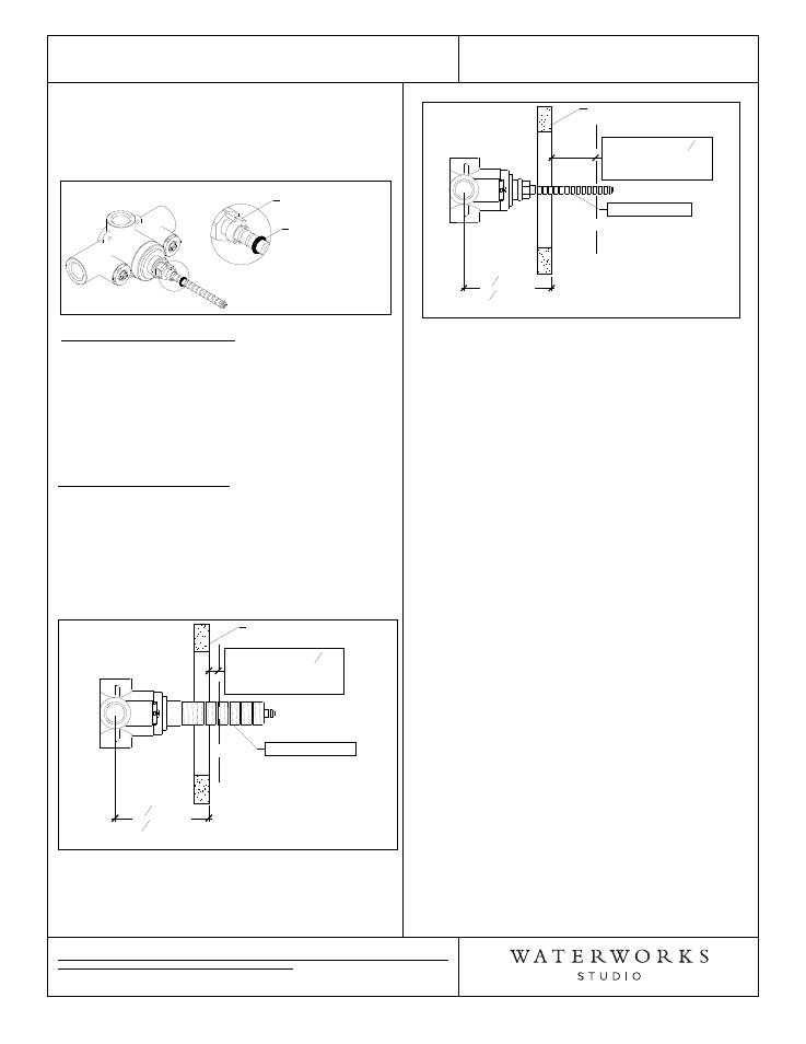
5. Slide the limit stop back onto the cartridge stem,
making sure to properly align it with the pin on the
cartridge bonnet. Slide the o-ring back to its original
position to prevent the limit stop from sliding off the
stem then turn the water off. See Figure-02
Figure - 02
Align limit stop to
the pin.
Slide o-ring down
to hold limit stop.
INSPECT THE CALIBRATION:
6. Turn the cartridge stem clockwise then turn the
water on and confirm the limit stop is functioning
properly by turning the stem counter-clockwise until
the limit stop prevents further rotation.
7. Verify the temperature to be the max temperature
set in Step 4. If it is not the correct temperature,
repeat the calibration process.
TRIM PLATE INSTALLATION:
8. Re-install the threaded tube and make a mark on the
tube that is 3/8" from the surface of the finished
wall.
9. Remove the tube then cut the tube at the mark
made in Step 8. DO NOT cut the end of the tube
with the internal threads. See Figure-03.
Figure - 03
Threaded Tube
Finished Wall
3
1
4
"MIN
4
1
4
"MAX
ROUGH-IN
CUT TUBE
3
8
"
FROM FINISHED
WALL
10. Mark then cut the cartridge stem 1-7/8" from the
surface of the finished wall. See Figure-04.
Figure - 04
Finished Wall
Cartridge Stem
3
1
4
"MIN
4
1
4
"MAX
ROUGH-IN
CUT STEM 1
7
8
"
FROM FINISHED
WALL
11. Re-install the threaded tube onto the valve.
12. Hold the trim plate (6) against the finished wall and
thread the trim connector (5) onto the threaded
tube and securely tighten to hold the trim plate
against the finished wall.
13. Hold the escutcheon (3) against the trim plate
making sure the washer (4) is behind the
escutcheon.
14. Thread the handle gland cover (1 or 2) onto the trim
connector (5) to secure the escutcheon against the
plate, making sure the handle is in the correct
orientation when fully threaded down.
¾
If further assistance is required, please contact
Product Support at 1-800-927-2120 (9am-6pm EST).