Installation guidelines – Waterworks Formwork Low Profile Three Hole Wall Mounted Lavatory Faucet with Metal Knob Handles User Manual
Page 2
PRODUCT SUPPORT 800.927.2120 8am - 6pm EST
FORMWORK
Low Profile Three Hole Wall Mounted Lavatory Faucet
Installation Guidelines
Page 2 of 4
Rev - 01
4.7.2014
These guidelines have been prepared for the professional contractor to aid in the installation of:
FORMWORK LOW PROFILE THREE HOLE WALL MOUNTED LAVATORY FAUCET WITH METAL KNOB HANDLES
(STYLE No. FMLS60) & METAL LEVER HANDLES (STYLE No. FMLS70)
All dimensions are based on original specification and are subject to change and variation.
Please consult your Design Associate for current specifications.
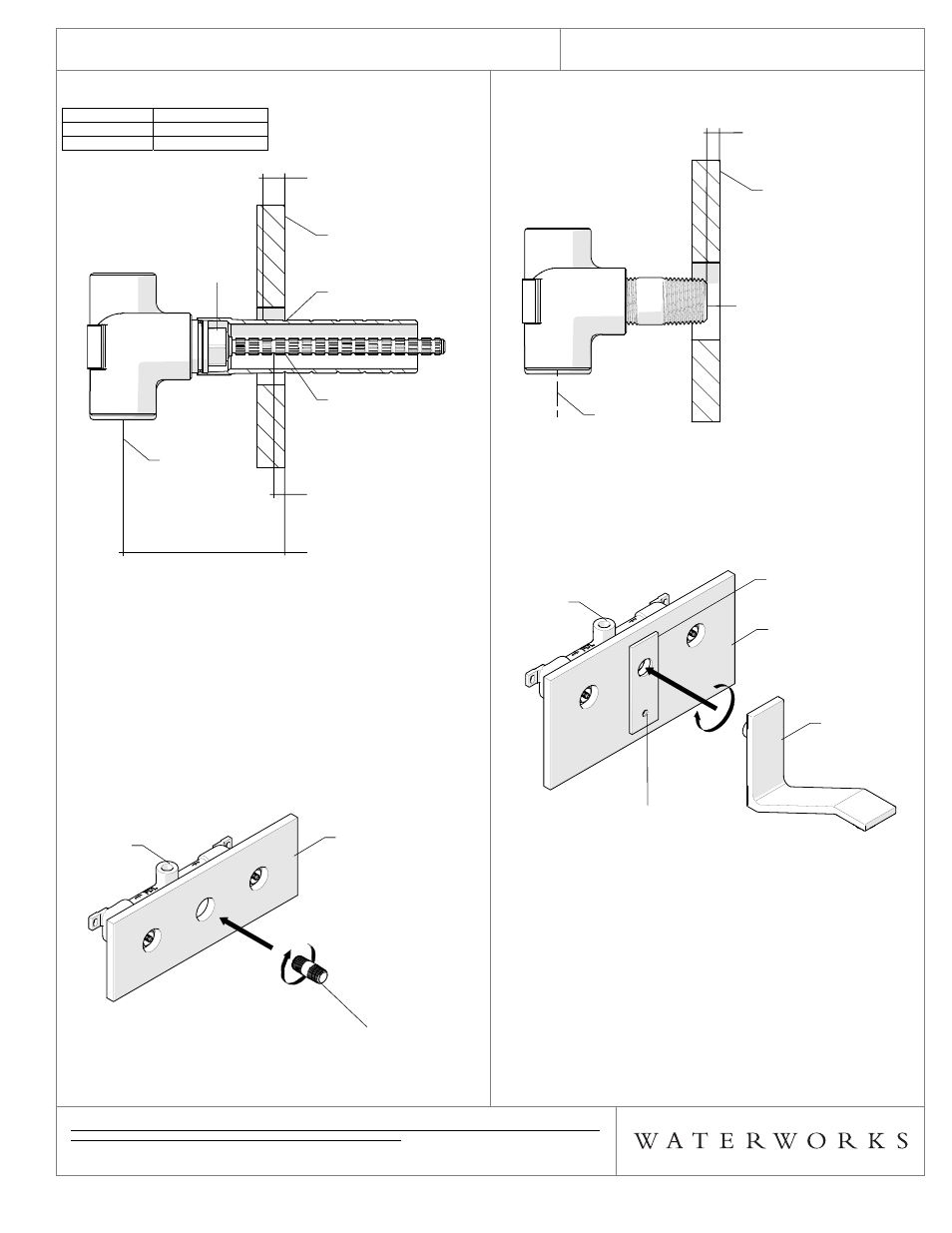
¾ See Figure - 02 for Steps 2 & 3
DIMENSION VALUE
(INCHES)
A 1/2"
B 1/16"
FIGURE - 02
2. Mark the THREADED TUBE as shown in Figure - 02
then remove and cut the THREADED TUBE.
3. Mark the CARTRIDGE STEM as shown in Figure - 02
then remove the CARTRIDGE and cut the CARTRIDGE
STEM.
4. Thread and securely tighten the CARTRIDGE and
THREADED TUBE back onto the VALVE.
5. Thread a 1/2" NPT x 1/2" NPT NIPPLE (NOT
INCLUDED) into the SPOUT OUTLET of the VALVE as
shown in Figure - 03.
FIGURE - 03
FINISHED WALL
THREADED
TUBE
CARTRIDGE
STEM
CARTRIDGE
CENTER OF
INLET
CENTER OF
INLET
"A"
CUT THREADED TUBE
BEHIND FINISHED WALL
"B"
CUT CARTRIDGE STEM
BEHIND FINISHED WALL
ROUGH-IN DEPTH
FINISHED WALL
THREADED
TUBE
CARTRIDGE
STEM
CARTRIDGE
CENTER OF
INLET
CENTER OF
INLET
FINISHED WALL
VALVE
1/2" NPT X 1/2" NPT NIPPLE
(NOT SUPPLIED)
FINISHED WALL
VALVE
1/2" NPT X 1/2" NPT NIPPLE
(NOT SUPPLIED)
6. Ensure the front face of NIPPLE is 3/16" from the
finished wall as shown in Figure - 04.
FIGURE - 04
7. Hold the ESCUTCHEON up to the finished wall and
thread the SPOUT onto the NIPPLE. Do not tighten the
SPOUT onto the NIPPLE. Mark where to drill the
required Ø1/2" hole using the pre-drilled hole on the
ESCUTCHEON as shown in Figure - 05.
FIGURE - 05
8. Remove the SPOUT and ESCUTCHEON and drill the
Ø1/2" hole using the mark made in Step 7.
9. Install the TOGGLE ANCHOR in the Ø1/2" hole drilled in
Step 8 then install the ESCUTCHEON using the SCREW
provided as shown in Figure - 06. Make sure to use the
RUBBER WASHERS provided to create a seal between
the finished wall and the ESCUTCHEON.
¾ If desired, a bead of caulk or a clear silicone may be
applied where the ESCUTCHEON contacts the finished
wall. DO NOT use putty.*
FINISHED WALL
1/2" NPT X 1/2" NPT NIPPLE
(NOT SUPPLIED)
CENTER OF
INLET
3/16"
FACE OF NIPPLE
BEHIND FINISHED WALL
FINISHED WALL
1/2" NPT X 1/2" NPT NIPPLE
(NOT SUPPLIED)
CENTER OF
INLET
FINISHED WALL
DRILL MARK
VALVE
ESCUTCHEON
SPOUT
FINISHED WALL
DRILL MARK
VALVE
ESCUTCHEON
SPOUT