Safety features, Block diagram/terminal configuration – Pilz PNOZ s4 C 48-240VACDC 3 n/o 1 n/c User Manual
Page 6
PNOZ s4
Operating Manual PNOZ s4
21396EN13
6
}
A connector can be used to connect 1 PNOZsigma contact expansion module
}
Operating modes can be set via rotary switch
}
LED indicator for:
–
Supply voltage
–
Input status, channel 1
–
Input status, channel 2
–
Switch status of the safety contacts
–
Start circuit
–
Errors
}
Plugin connection terminals (either springloaded terminal or screw terminal)
Safety features
The relay meets the following safety requirements:
}
The circuit is redundant with builtin selfmonitoring.
}
The safety function remains effective in the case of a component failure.
}
The correct opening and closing of the safety function relays is tested automatically in
each onoff cycle.
}
The unit has an electronic fuse.
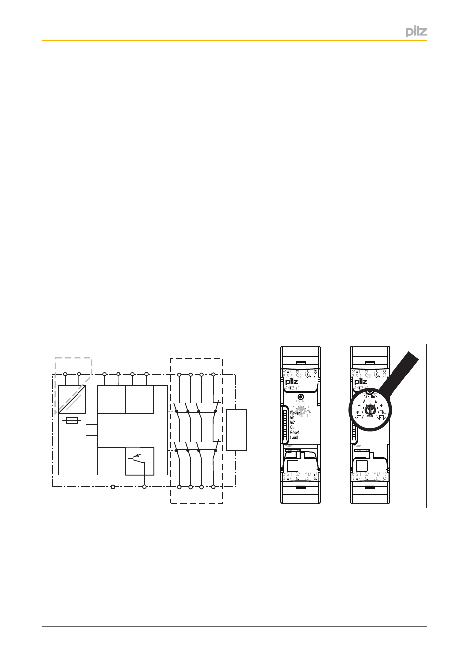
Block diagram/terminal configuration
Input
Input
A1
A2
S21 S22
=
Power
Reset/
Start
S34
S11 S12
=
Y32
(~)
K1
K2
13 23 33
24 34
14
41
42
Interface
expansion
unit
( )
*
*
Fig.: Rotary cam arrangement monitoring Front view with cover, right: Front view without cover
Grey highlighted area: Applies only with U
B
= 48 – 240 V AC/DC
*Insulation between the nonmarked area and the relay contacts: Basic insulation (over
voltage category III), Protective separation (overvoltage category II)