Installation fhr-35 pan and tilt head robotic – Vinten Radamec FHR-35 User Manual
Page 11
Installation
FHR-35
Pan and Tilt Head
Robotic
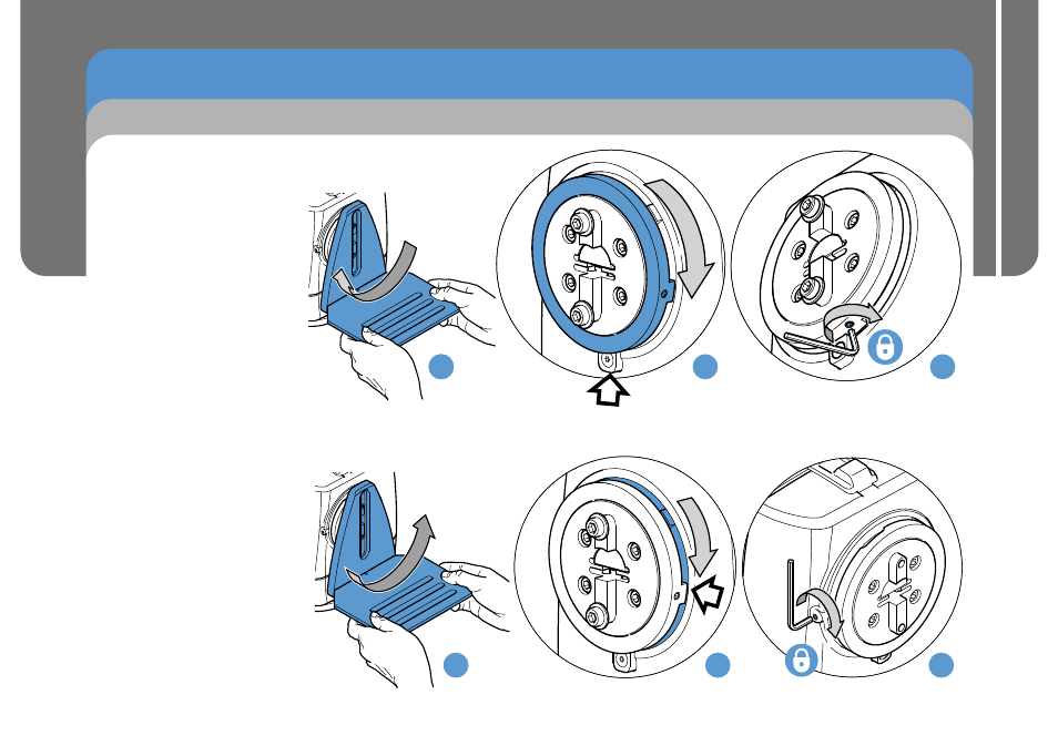
Setting the Tilt Mechanical Hard Stops
9
1.
(a) Place the camera cradle
over the tilt mounting.
Move the tilt mounting in
a clockwise direction to
the required maximum
limit of movement.
(b) Remove the camera
cradle. Move the large
outer ring clockwise until
it rests on the fixed stop.
(c) Secure the grub screw
into position using a
2.5 mm Allen key. Tighten
the screw to a minimum
of 1.5 Nm (13.3 lbf-in.).
2.
(a) Place the camera cradle
over the tilt mounting.
Move the tilt mounting in a
counterclockwise direction
to the required minimum
limit of movement.
(b) Remove the camera
cradle. Move the inner ring
clockwise until it rests on
the large outer ring stop.
(c) Secure the grub screw into
position using a 2.5 mm
Allen key. Tighten the
screw to a minimum of
1.5 Nm (13.3 lbf-in.).
a
b
c
a
b
c
a
Installation and Configuration Guide