7 cable grounding, 1 serial communications, 2 digital i/o - coming soon – Rice Lake Counterpart Configurable Counting Indicator - User Manual - Version 1.0 User Manual
Page 14: Serial communications, Digital i/o - coming soon
8
Counterpart User Manual
2.7
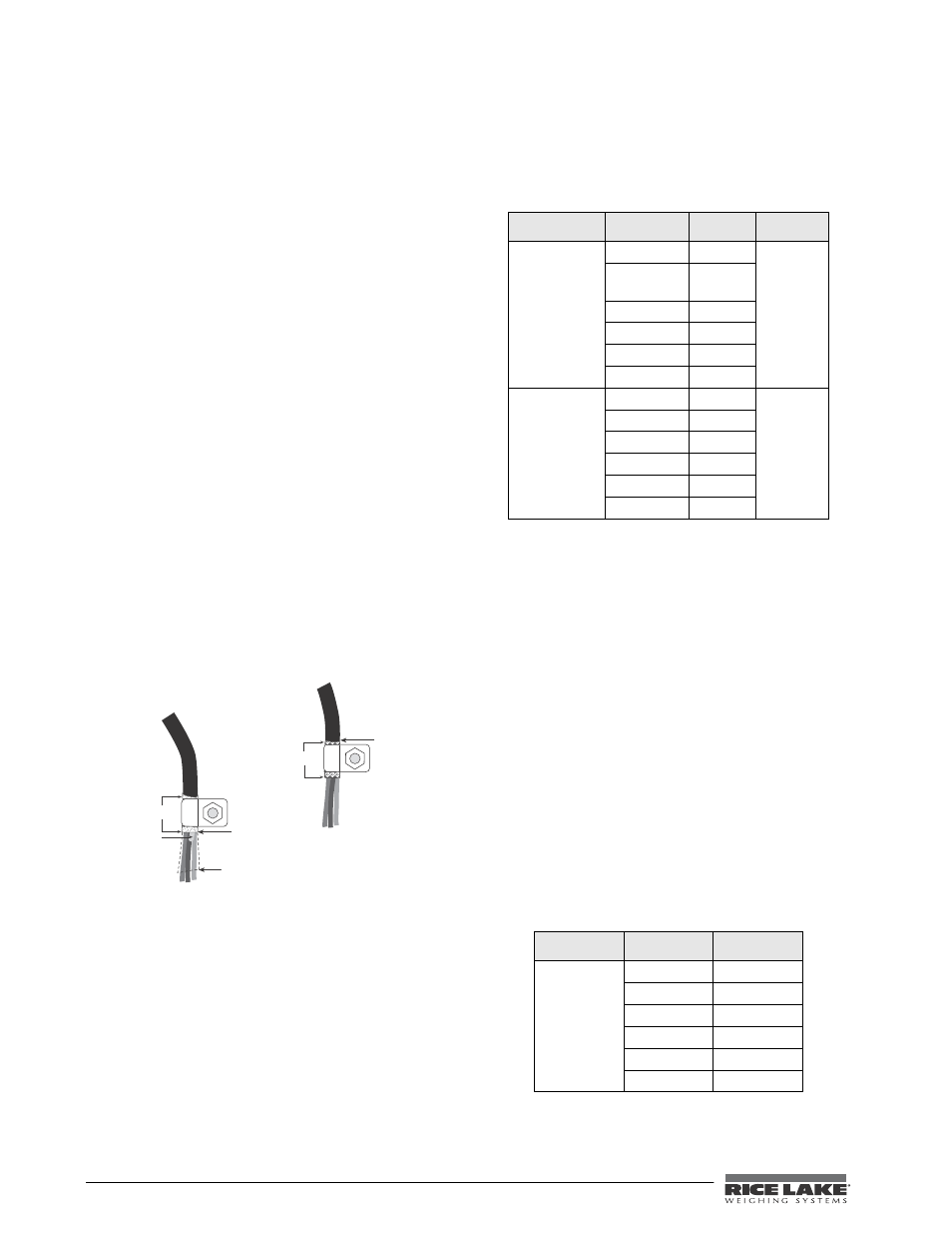
Cable Grounding
Except for the power cord, all cables should be
grounded against the scale enclosure. Do the
following to ground shielded cables.
•
Use the lockwashers, clamps, and kep nuts
provided in the parts kit to install grounding
c l a m p s o n t h e e n c l o s u r e s t u d s . I n s t al l
grounding clamps that will be used; do not
tighten nuts.
•
Route cables and grounding clamps to
determine cable lengths required to reach
cable connectors. Mark cables to remove
insulation and shield as described below:
•
For cables with foil shielding, strip insulation
and foil from the cable half an inch (15 mm)
past the grounding clamp (see Figure 2-1).
Fold the foil shield back on the cable where
the cable passes through the clamp. Ensure
silver (conductive) side of foil is turned
outward for contact with the grounding
clamp.
•
For cables with braided shielding, strip cable
insulation and braided shield from a point just
past the grounding clamp. Strip another half
inch (15 mm) of insulation only to expose the
braid where the cable passes through the
clamp (see Figure 2-1 8).
•
Finish installation using cable mounts and ties
to secure cables inside of indicator enclosure.
Figure 2-1. Grounding Clamp Attachment for Foil-Shielded
and Braided Cabling
2.7.1
Serial Communications
Wire the serial communications cables to J4, which is
Port 2 (5-wire RS-232 port). J5 is Port 1 (RS-232 and
20 mA). Connect communications cables to J5 and J4
as shown in Table 2-3.
Use cable ties to secure serial cables to the inside of
the enclosure.
Port 1 supports full duplex RS-232 communications
only; Port 2 provides either active 20 mA output or
d u p l e x R S - 2 3 2 t r a n s m i s s i o n . B o t h p o r t s a r e
c o n f i g u r e d u s i n g t h e S E R I A L m e n u . S e e
Section 3.6.5 on page 31.
Table 2-3. J4 and J5 Pin Assignments
2.7.2
Digital I/O - COMING SOON
The Digital I/O can be configured as either digital
inputs or digital outputs as determined by the DIO
menu (see Section 3.6.5 on page 31). The inputs are
active (on) with low voltage (0 VDC) and can be
driven by TTL or 5V logic without additional
hardware. Use the DIG I/O menu (see Section 3.6.5
on page 31) to configure the digital inputs. LEDs on
the CPU board light when digital inputs are active (see
Figure 2-2).
Digital outputs are typically used to control relays that
drive other equipment. Outputs are designed to sink
not source, switching current. Each output is a CMOS
circuit, capable of sinking 24 mA when active. Digital
outputs are wired to switch relays when the digital
output is active (low, 0 VDC) with reference to 5
VDC supply. LEDs on the CPU board light up when
the digital outputs are active (see Figure 2-2).
Table 2-4. J3 Pin Assignments (Digital I/O)
Insulated cable
Foil (silver side out)
Grounding clamp
Shield wir e (cut)
Length of foil before folding
back on cable insulation
Cut insulation here
for foil-shielded cables
Braid
Cut insulation here
for braided cables
NOTE:
Install lockwashers
first, against backplate,
under grounding clamp
Connector
Pin
Signal
Port
J4
1
20 mA
2
2
Ground or
-20 mA
3
Tx
4
Rx
5
CTS
6
RTS
J5
1
Ground
1
2
Ground
3
Tx
4
Rx
5
DTR
6
RTS
Connector
Pin
Signal
J3
1
+5V
2
Ground
3
DIG I/O 1
4
DIG I/0 2
5
DIG I/O 3
6
DIG I/O 4