P30-corner-mull-layout – Oldcastle BuildingEnvelope Reliance-HTC User Manual
Page 33
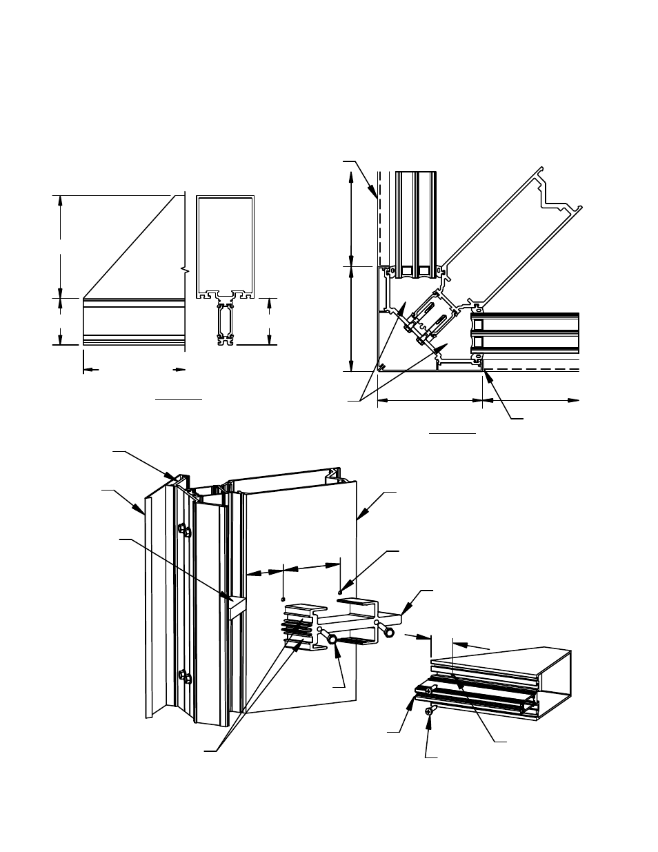
FIGURE 28 shows the basic layout of the standard one−piece corner mullion assembly. These details are for
general reference and do not necessarily reflect all conditions. For specific assembly, sealing and anchoring
notes, refer to approved shop drawings. See Parts List for specific part numbers.
Detail "A"
Miter Cut at Horizontal
(1 3/4" Glazing)
Varies
2 1/32"
Cut length = D.L.O.
(see DETAIL "B")
Detail "B"
Captured OS 90 Corner
Assembly Guide
FIGURE 28
Captured OS 90 Corner Assembly
(Cut lengths in parentheses)
2 1/32"
D.L.O.
2
1/2"
2 1/2"
D
.L
.O
.
WW-110 face cover
(DLO minus 1/16")
Zone plug
(typ. both sides)
WW-162
pressure plate
(DLO minus 1/4")
Face cover
(continuous)
Pressure plate
(continuous)
Corner mullion
#11 (.191 dia) tap hole
for #14 fastener
Match drill shear block with
5/32" dia drill for #10 screw
Corner shear block
FS-9 (2)
Straight cut at glass pocket
(Refer to DETAIL 'A' above)
FS-115 (2)
#11 (.191 dia) clear
hole for #10 screw
2 1/16" 2
5/8"
1 1/8"
Zone plug
CORNER MULLION
R E L I A N C E − H T C I N S T A L L A T I O N M A N U A L
MAY 2013
30
Phone: 1-866-OLDCASTLE (653-2278)
Web Address: www.oldcastlebe.com