Kontron ETXexpress-AI User Manual
Page 64
Kontron ETXexpress-AI User’s Guide
59
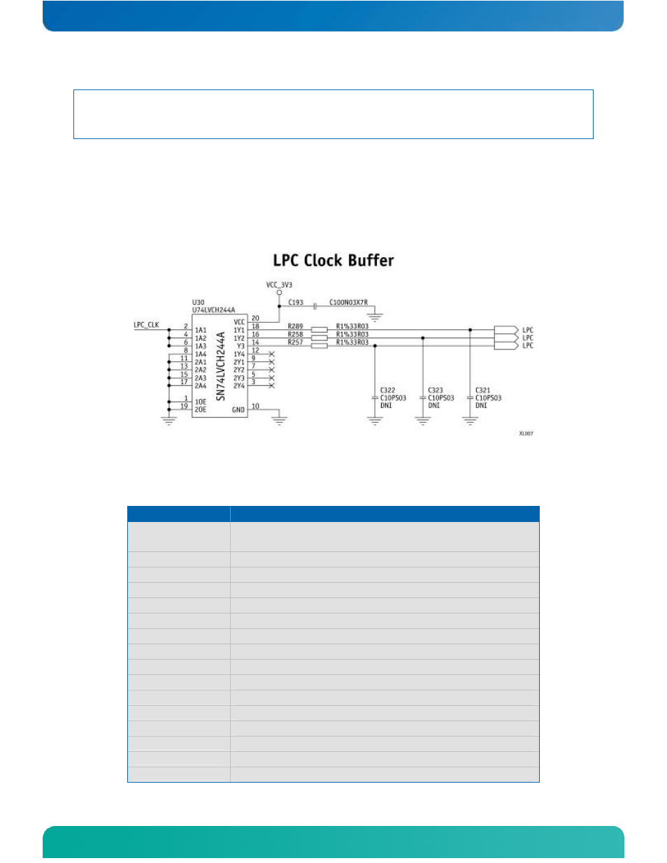
NOTE: When using a standard clock buffer on the baseboard, be aware that the
generated delay must be considered for the length matching of the
layout.
Clock Buffer Reference Schematic
The schematic in Figure 7 shows an implementation example for the clock
buffer.
Figure 7: LPC Clock Buffer
Table 14: LPC Addresses
Address (HEX)
Device
0000 - 00FF
IBM PC-compatible devices (IRQ-controller,
keyboard, RTC etc.)
002E-002F
Optional: Super I/O W83627
004e - 004f
TPM
01F0 - 01F7
Fixed disk
03C0 - 03CF
VGA/EGA compatible registers
03F6
Fixed disk
0400 - 043F
SMBus
0480 - 04BF
GPIO SCH
04D0 - 04D1
IRQ configuration
08F0 - 08FF
Optional
0900 - 091F
Power Management
0A80 - 0A83
Reserved
0CF8 - 0CFF
PCI configuration
D880 - D887
PCI LAN Controller *
E080 - E09F
PCI USB Controller *
E480 - E49F
PCI USB Controller *
- CP3003-SA uEFI BIOS (72 pages)
- CP3003-SA (36 pages)
- CP3002 (38 pages)
- CP3002-RC uEFI (64 pages)
- CP-RIO3-05 (42 pages)
- CP3002-RC (30 pages)
- CP342 (52 pages)
- CP930 (46 pages)
- CP932 (52 pages)
- CP346 (72 pages)
- CP384 (66 pages)
- CP383 (74 pages)
- CP382 (58 pages)
- CP381 (60 pages)
- CP372 (64 pages)
- CP371 (60 pages)
- CP-RIO3-04S (38 pages)
- CP390 (36 pages)
- CPS3410 (9 pages)
- CPS3402 (9 pages)
- CPS3105 (9 pages)
- CPS3101 (9 pages)
- CPS3003-SA (19 pages)
- PB-SIO4 (34 pages)
- PB-SIO4A (34 pages)
- PB-DOUT8 (34 pages)
- VMOD-2 (82 pages)
- VSBC-32 (110 pages)
- VM42 (62 pages)
- Bootstrap Loader (24 pages)
- VMP1 with Netbootloader (120 pages)
- VMP1 (106 pages)
- NetBootLoader (86 pages)
- VMP2 (142 pages)
- VMP3 (154 pages)
- CP-RIO6-923 (32 pages)
- CP-RIO6-923-F (32 pages)
- CP-RIO6-001 (28 pages)
- CP-RIO6-001-HD-VGA (46 pages)
- CP-RIO6-M (20 pages)
- CP-RIO6-B (28 pages)
- CP6925 (42 pages)
- CP6002 uEFI BIOS (76 pages)
- CP6002 IPMI (40 pages)
- CP6002 (42 pages)