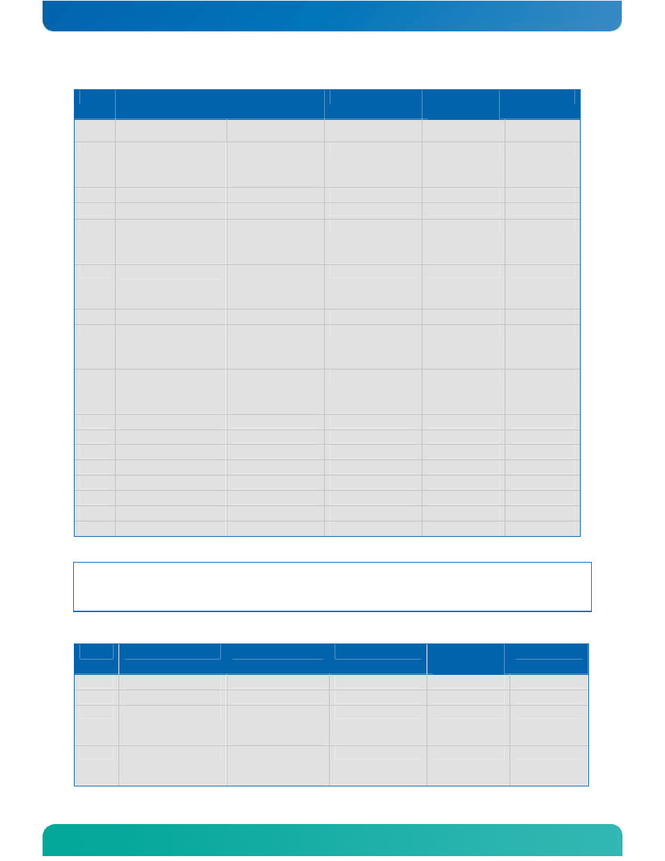
Table 10: type 6 connector x1b - row d – Kontron ETXexpress-AI User Manual
Page 51
Kontron ETXexpress-AI User’s Guide
46
Pin
Signal
Description
Type
Terminatio
n
Comment
Receive Lane
13 Positive
C95
PEG_RX13-
PCI Express
Graphics
Receive Lane
13 Negative
DP-I
C96
GND
Power Ground
PWR
-
-
C97
RSVD
Reserved
Not connected nc
nc
C98
PEG_RX14+
PCI Express
Graphics
Receive Lane
14 Positive
DP-I
C99
PEG_RX14-
PCI Express
Graphics
Receive Lane
14 Negative
DP-I
C100
GND (Fixed)
Power Ground
PWR
-
-
C101
PEG_RX15+
PCI Express
Graphics
Receive Lane
15 Positive
DP-I
C102
PEG_RX15-
PCI Express
Graphics
Receive Lane
15 Negative
DP-I
C103
GND
Power Ground
PWR
-
-
C104
VCC_12V
12V VCC
PWR
-
-
C105
VCC_12V
12V VCC
PWR
-
-
C106
VCC_12V
12V VCC
PWR
-
-
C107
VCC_12V
12V VCC
PWR
-
-
C108
VCC_12V
12V VCC
PWR 8
-
-
C109
VCC_12V
12V VCC
PWR
-
-
C110
GND (Fixed)
Power Ground
PWR
-
-
Note: The termination resistors in this table are already mounted on the
ETXexpress® board. Refer to the PICMG COM Express™ Design Guide for
information about additional termination resistors.
Table 10: Type 6 Connector X1B - Row D
Pin
Signal
Description
Type
Terminatio
n
Comment
D1
GND (Fixed)
Power Ground
PWR
-
-
D2
GND
Power Ground
PWR
-
-
D3
USB_SSTX0-
SuperSpeed USB
Data Transmit
Path 0-
Not connected
nc
nc
D4
USB_SSTX0+
SuperSpeed USB
Data Transmit
Path 0+
Not connected
nc
nc