4 signal descriptions – Kontron ETXexpress-AI User Manual
Page 59
Kontron ETXexpress-AI User’s Guide
54
4.3.4
Connector J2 - Fan
This is a 4-pin connector for a 5V fan. J2 can be configured in the BIOS
setup. See Section 6.2, “Onboard Fan Connector” for more detailed
information.
4.4
Signal Descriptions
4.4.1
PCI Express Interface
The PCI Express* x1 lane is a fast connection interface for many different
system devices, such as network controllers, I/O controllers or express card
devices. The implementation of this subsystem complies with the COM Express™
specification. Refer to the PICMG COM Express™ Design Guide for additional
implementation information.
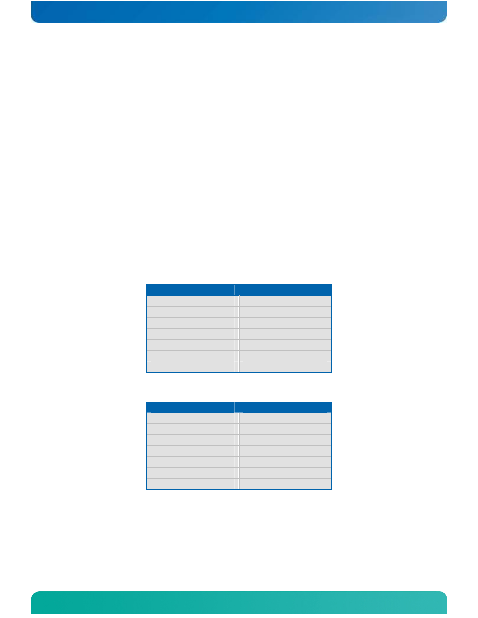
The ETXexpress®-AI COM supports up to 7 PCI Express x1 lanes. See Table 11
and Table 12 for detailed configuration information.
Table 11: PCI Express Configuration (Type 2)
Source
Target
Intel PCIe lane 1 COMe PCIe lane 0
Intel PCIe lane 2 COMe PCIe lane 1
Intel PCIe lane 3 COMe PCIe lane 2
Intel PCIe lane 4 COMe PCIe lane 3
Intel PCIe lane 5 COMe PCIe lane 4
Intel PCIe lane 6 COMe PCIe lane 5
Intel PCIe lane 7 COMe PCIe lane 6
Table 12: PCI Express Configuration (Type 6)
Source
Target
Intel PCIe lane 1 COMe PCIe lane 0
Intel PCIe lane 2 COMe PCIe lane 1
Intel PCIe lane 3 COMe PCIe lane 2
Intel PCIe lane 4 COMe PCIe lane 3
Intel PCIe lane 5 COMe PCIe lane 4
Intel PCIe lane 6 COMe PCIe lane 5
Intel PCIe lane 7 COMe PCIe lane 6
4.4.2
USB Interface
The USB interface supports up to eight USB 2.0 ports. Table 13 shows the USB
configuration for the ETXexpress®-AI module.