Replacing defective processor module, Installation – Carrier 040-420 User Manual
Page 73
4
OUT
S W I T C H
M O D U L E
_
_
_
AND ASSOCIATED MODULAR UNITS
-
-
-
-
2
FLOTRONIC’” II UNITS
T B
Terminal Block
NOTE: The
Flotronic II units require the acces-
sory options module for this feature
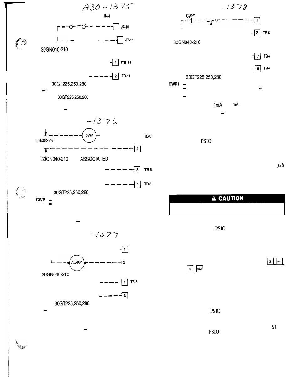
Fig. 33
Remote Dual Set Point Control
-
-
-
-
-
- c l
3
4
T5-3
AND
MODULAR UNITS
3
4
FLOTRONIC II UNITS
Chilled Water Pump
T B
Terminal Block
NOTE: The maximum load allowed for the chilled water pump circuit
is 125 va sealed, 1250 va inrush at 115 or 230 v
Fig. 34
Chilled Water Pump
ALARM SHUTOFF
S W I T C H
I -
-
-
-
-
-
-
-
a
-
-
-
1 TB-3
I
i
T 8 - 3
c
l
AND ASSOCIATED MODULAR UNITS
2 TB-5
FLOTRONIC II UNITS
TB
T e r m i n a l B l o c k
NOTE: The maximum load allowed for the alarm circuit is 125 va
sealed, 1250 va inrush at 115 or 230 v
Fig. 35
Remote Alarm
7 3
(CWFS)
TB-6
I - -
-
-
-
-
- -
-
- -
-
-
AND ASSOCIATED MODULAR UNITS
- - - - -
7
-
-
-
-
-
8
FLOTRONIC I I UN ITS
Chilled Water Pump Interlock
CWFS
Chilled Water Flow Switch (not required low flow
protection is provided by Flotronic II controls)
T B
Terminal Block
NOTE: Contacts must be rated for dry circuit application, capable of
reliably switching a 5 vdc,
to 20
load.
Fig. 36
Interlocks
REPLACING DEFECTIVE
PROCESSOR MODULE
The replacement part number is printed on a small label
on front of the
module. The model and serial num-
bers are printed on the unit nameplate located on an exte-
rior corner post. The proper software and unit configuration
data is factory installed by Carrier in the replacement mod-
ule. Therefore, when ordering a replacement processor mod-
ule (PSIO), specify complete replacement part number,
unit model number, and serial number. If these numbers
are not provided, the replacement module order is config-
ured instead as a generic Flotronic’” 11 replacement mod-
ule. This requires reconfiguration of the module by the
installer.
Electrical shock can cause personal injury, Disconnect
all electrical power before servicing.
Installation
1.
2.
3 .
4 .
5 .
6 .
7 .
Verify the existing
module is defective by using
the procedure described in the Control Modules sec-
tion on page 64.
Refer to Start-Up Checklist for Flotronic II Chiller Sys-
tems (completed at time of original start-up) found in
job folder. This information is needed later in this
procedure. If checklist does not exist, fill out the
and
configuration code sections on a new check-
list. Tailor the various options and configurations as
needed for this particular installation.
Check that all power to unit is off. Carefully discon-
nect all wires from defective module by unplugging the
6 connectors. It is not necessary to remove any of the
individual wires from the connectors. Remove the green
ground wire.
Remove defective
by removing its mounting screws
with a Phillips screwdriver, and removing the module
from the control box, Save the screws for later use.
Use a small screwdriver to set address switches and
S2 on the new
module to exactly match the set-
tings on the defective module.
Package the defective module in the carton of the new
module for return to Carrier.
Mount the new module in the unit control box using a
Phillips screwdriver and the screws saved in Step 4 above.