Carrier 040-420 User Manual
Page 65
DRIVER)
( L I D ) ( 4
Fig.
Sensor Bus Wiring
(Communications)
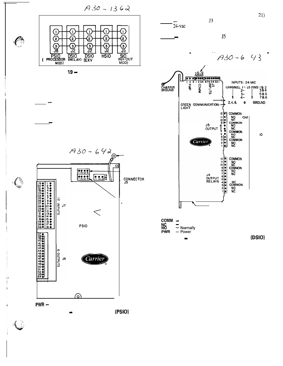
PROCESSOR MODULE (PSIO) (Fig. 20)
Inputs
Each input channel has 3 terminals; only 2 of the
terminals are
used.
Application of machine determines which
terminals are used. Always refer to individual unit wiring
for terminal numbers.
Outputs
Output is 24 vdc. There are 3 terminals, only 2
of which are used, depending on application. Refer to unit
wiring diagram.
NOTE: Address switches (see Fig. 20) must be set at 01
(different when CCN connected).
C H A S S I S
G R O U N D
0
Power
A D D R E S S
0
S W I T C H E S
0
I -
-( REAR)
N E T W O R K
(FORWARD)
S E N S O R B U S
C O N N E C T O R
J8
Fig. 20
Processor Module
6 5
LOW VOLTAGE RELAY MODULE (DSIO) (Fig.
Inputs
Inputs on strip are discrete inputs (ON/OFF).
When
power is applied across the 2 terminals in a
channel it reads as on signal. Zero v reads as an off signal.
Outputs
Terminal strips J4 and
are internal relays whose
coils are powered-up and powered-off by a signal from micro-
processor. The relays switch the circuit to which they are
connected. No power is supplied to these connections by
DSIO module.
S E N S O R B U S C O N N E C T O R
RED STATUS LIGHT
AND ARE
(C)
I
RELAYS
I
COMMON
NO
NEL I2
I I
9
8
7
6
5
A D D R E S S A D J U S T M E N T
(NOT SHOWN) ON UNDERSIDE
LEGEND
Communications Bus
Normally Closed
Open
Fig. 21
Low-Voltage Relay Module