Att clt, Clt qt t cl cl t c lt c lt, C lt t – Carrier 040-420 User Manual
Page 35: C lt c l
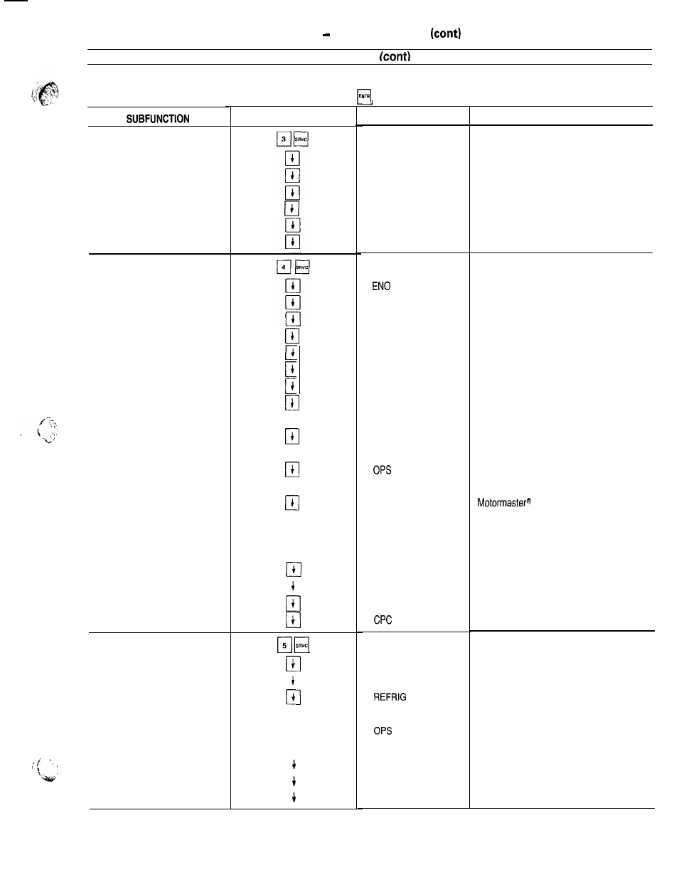
Table 9
Keypad Directory
SERVICE
The next 3 subfunctions provide the ability to modify configurations Refer to separate Installation, Start-Up, and Service Instructions
supplied with unit for further information on c h a n g i n g c o n f i g u r a t i o n s .
To change a configuration, enter the new configuration and press
while on the correct configuration.
3 FACTORY
CONFIGURATION
4 FIELD
CONFIGURATION
5 SERVICE
CONFIGURATION
KEYPAD ENTRY
t
t
t
t
t
c lt
t
qt
t
att
clt
clt
qt
t
cl
cl
t
c lt
c lt
c lt
c l
q
cl
DISPLAY
COMMENT
FACT CFG
x x x x x x x x
x x x x x x x x
x x x x x x x x
x x x x x x x x
x x x x x x x x
x x x x x x x x
Factory Configuration Codes
Configuration Code 1
Configuration Code 2
Configuration Code 3
Configuration Code 4
Configuration Code 5
Configuration Code 6
FLD CFG
X
B U S X
BAUD X
FLUID X
UNITS X
LANG X
NULA X
NULB X
HGB X
S E Q T X
SEQF X
x
HEADM X
M M X
CSPTYP X
CRTYP X
E R T Y P X
L S T Y P X
RAMP X
LOCK X
x
A d j u s t a b l e F i e l d C o n f i g u r a t i o n
CCN Element Address
CCN Bus Number
CCN Baud Rate
C o o l e r F l u i d S e l e c t
Display Unit Select
Display Language Select
No Circuit A Unloaders
No. Circuit B Unloaders
Hot Gas Bypass Select
L o a d i n g S e q u e n c e S e l e c t
Lead/Lag Sequence Select
Oil Pressure Switch Select
Head Pressure Control Method
Select
C o o l i n g S e t P o i n t C o n t r o l S e l e c t
Cooling Reset Control Select
External Reset Sensor Select
Demand Limit Control Select
Ramp Load Select
Cooler Pump Interlock Select
Cooler Pump Control Select
SRV CFG
x x x x x x x x
x x x x x x x x
X
T D T Y P X
x
LPS x
FANTYP X
SH X
M O P X
Service Configurations
Configuration Code 7
Configuration Code 8
Refrigerant
Pressure Transducer Select
Oil Transducer Set Point
Low Pressure Set Point
F a n S t a g i n g S e l e c t
EXV Superheat Set Point
EXV MOP Set Point
3 5