Carrier 040-420 User Manual
Page 26
Head Pressure Control
The microprocessor con-
trols the condenser fans in order to maintain the lowest con-
densing temperature possible, thus the highest unit efficiency.
Instead of using the conventional head pressure control meth-
ods, the fans are controlled by the position of the EXV and
suction superheat.
As the condensing temperature drops, the EXV opens to
maintain the proper suction superheat. Once the EXV is
fully open, if the condensing temperature continues to drop,
the suction superheat begins to rise. Once the suction super-
heat is greater than 40 F (22.2 C), a fan stage is removed
after 2 minutes,
As the condensing temperature rises, the EXV closes to
maintain the proper suction superheat. Once the EXV has
closed to 39.5% open (300 steps open), a fan stage is added
after 2 minutes.
During start-up, all the condenser fans are started when
the condensing temperature reaches 95 F (35 C) to prevent
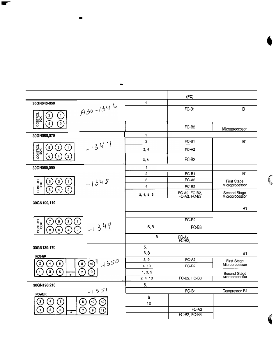
excessive discharge pressure during pulldown. See Table 5
for condenser fan sequence of operation.
Table 5
Condenser Fan Sequence
FAN ARRANGEMENT
FAN NUMBER(S)
FAN CONTACTOR
CONTROLLED BY
I
FC-Al
2
3
FC-A2
Compressor Al
Compressor
First Stage
Microprocessor
4
Second Stage
FC-Al
I
Compressor Al
Compressor
First Stage
Microprocessor
Second Stage
Microprocessor
FC-Al
Compressor Al
Compressor
(and associated modular units)
1
FC-Al
Compressor Al
2
F C - 8 1
Compressor
3
F C - A 2
First Stage
4
Microprocessor
5, 7,
FC-AS,
Second Stage
Compressor
(and associated modular units)
3, 4, 5, 6, 7,
FC-A3 ,
T h i r d Stage
FC-B3
Microprocessor
7
FC-Al
Compressor Al
FC-Bl
Compressor
FC-A2, FC-A3
(and associated modular units)
7
I
FC-Al
I
Compressor Al
6 . 8
I
I
3,
FC-A2
Frist Stage
4,
FC-B2
Microprocessor
1 , 3, 9, 11
FC-A2,
Second Stage
2, 4 , 10, 1 2
Microprocessor
*Control box.
26