Carrier 040-420 User Manual
Page 27
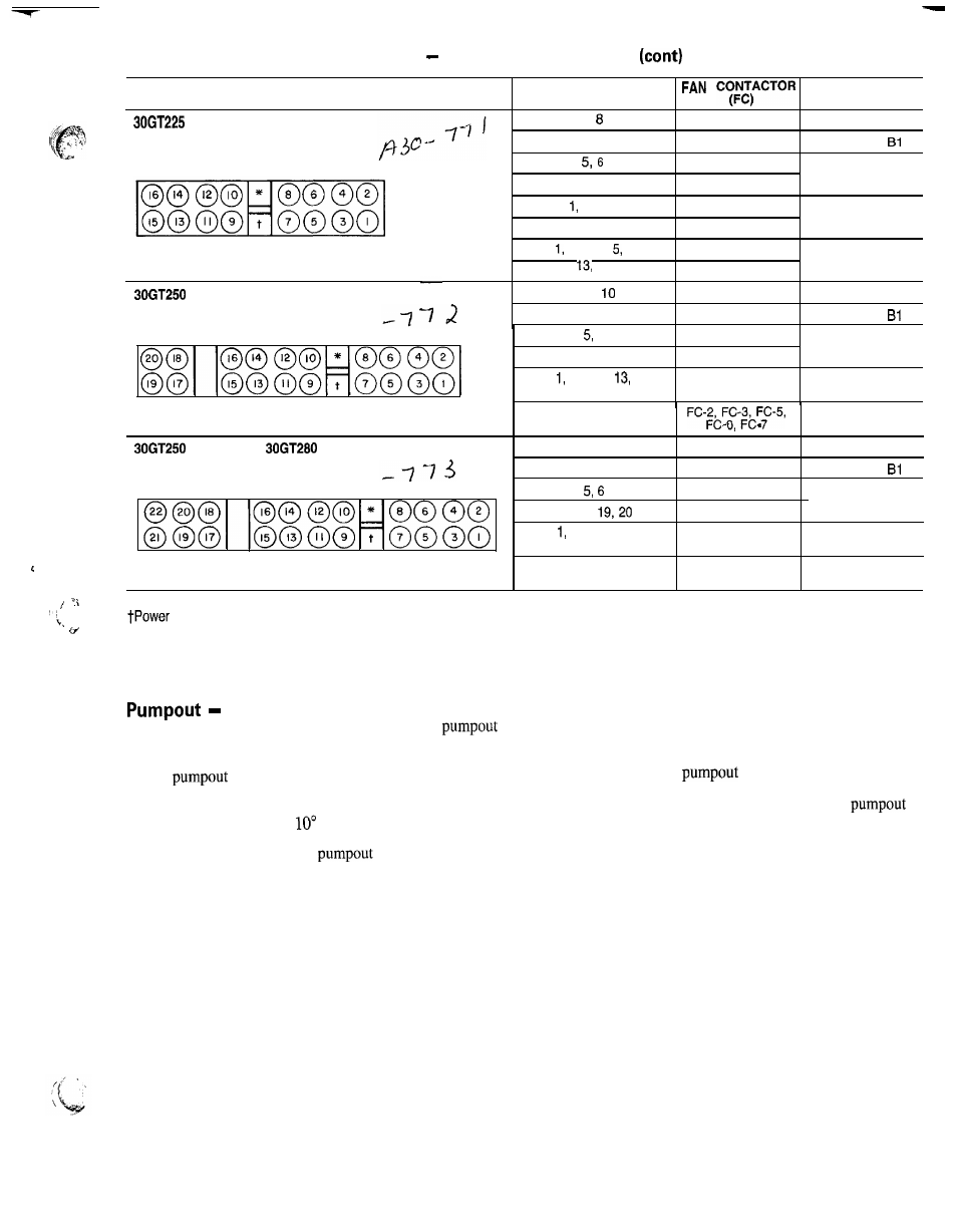
Table 5
Condenser Fan Sequence
FAN ARRANGEMENT
FAN NUMBER(S)
CONTROLLED BY
(60 Hz)
7,
FC-1
Compressor Al
9, 1 0
FC-4
Compressor
FC-2
First Stage
11, 1 2
FC-5
Microprocessor
2, 3 , 4
FC-3
Second Stage
13, 14, 15, 16
FC-6
Microprocessor
2, 3, 4, 6
FC-2, FC-3
T h i r d S t a g e
11, 12,
14, 15, 1 6
FC-5, FC-6
Microprocessor
7, 8,
F C - 1
Compressor Al
9, 17, 1 8
FC-4
Compressor
6
11, 12, 19
2, 3, 4,
14, 15, 16, 20
FC-2
First Stage
FC-5
Microprocessor
Second Stage
FC-3, FC-6,
FC-7
Microprocessor
1 , 2, 3, 4, 5, 6, 11, 12, 13,
T h i r d S t a g e
14, 15, 16, 19, 2 0
Microprocessor
(50 Hz) AND
7, 8, 1 0
FC-1
Compressor Al
9, 17, 1 8
FC-4
Compressor
FC-2
II, 12,
FC-5
First Stage
Microprocessor
2, 3, 4, 13,
Second Stage
14, 15, 16, 21, 22
FC-3, FC-6, FC-7
Microprocessor
1, 2, 3, 4, 5, 6, 11, 12, 13,
FC-2, FC-3, FC-4,
T h i r d S t a g e
14, 15, 16, 19, 20, 21, 2 2
FC-5, FC-6, FC-7
Microprocessor
*Control box.
box.
When the lead compressor in each circuit
saturated suction temperature is below -15 F (-26 C). At
is started or stopped, that circuit goes through a
this point, the EXV starts to open and continues to open
cycle to purge the cooler and refrigerant suction lines of
gradually to provide a controlled start-up to prevent liquid
refrigerant.
flood-back
to
the compressor.
The
cycle starts immediately upon starting the
lead compressor and continues until the saturated suction
temperature is 10” F (5.5” C) below the saturated suction
temperature at start-up, is
F (5.5” C) below the cooler
leaving fluid temperature, or reaches a saturated suction tem-
perature of -15 F (-26 C). No
is necessary if the
At shutdown, the
cycle continues until the sat-
urated suction temperature for that circuit is 10” F (5.5” C)
below the saturated suction temperature when
is
initiated, or saturated suction temperature reaches -15 F
(-26 C). At that point, the compressor shuts down and the
EXV continues to move until fully closed.
27