Elest – Carrier 040-420 User Manual
Page 28
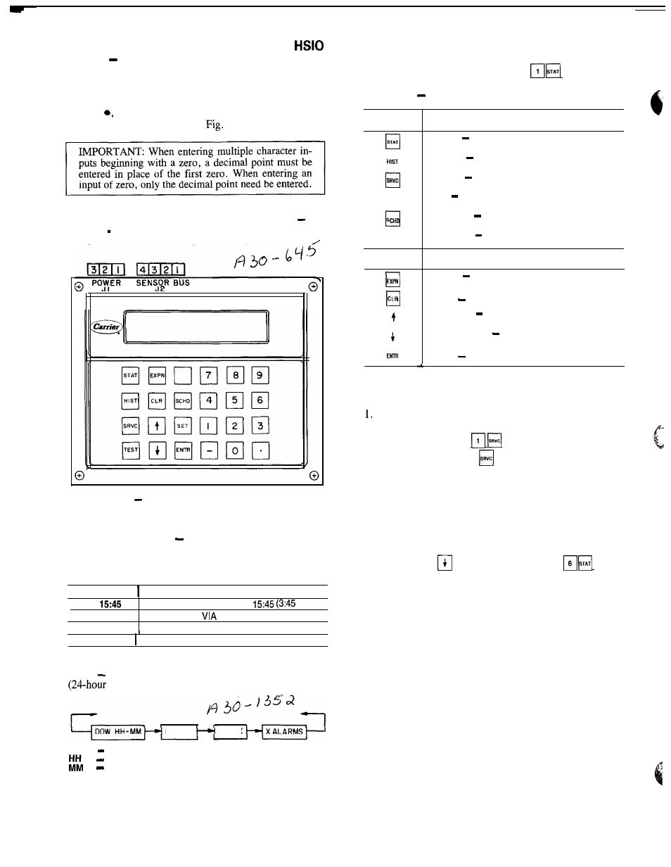
Keypad and Display Module (Also Called
or LID)
The only function of this module is to allow
the operator to communicate with the processor. It is used
to enter configurations and set points and to read data, per-
form tests, and set schedules. This device consists of a key-
pad with 6 function keys, 5 operative keys, 12 numeric keys
(0 to 9,
and -), and an alphanumeric g-character LCD
(liquid crystal display). See
3. See Table 6 for
key usage.
ACCESSING FUNCTIONS AND SUBFUNCTIONS See
Tables 6 8. Table 7 shows the 6 functions (identified by
name) and the subfunctions (identified by number).
Fig. 3
Keypad and Display Module
SUMMARY DISPLAY
When keypad has not been used
for 10 minutes, display automatically switches to the rotat-
ing summary display. This display has 4 parts, listed be-
low, which appear in continuous rotating sequence.
DISPLAY
E X P A N S I O N
TUE
CLOCK ON
C O O L 1
TODAY IS TUE, TIME IS
PM)
UNIT IS ON
CLOCK SCHEDULE
NUMBER OF STAGES IS 1
2 ALARMS 2 ALARMS DETECTED
AUTOMATIC DISPLAY OPERATION/DEFAULT DIS-
PLAY In this mode, the keypad displays the current time
format), current operating modes, cooling capac-
ity stages, and total number of alarms.
MODE X
COOL x
The default display is displayed every 2 seconds if there
has been no manual input from the keypad for 10 minutes.
To return to automatic display, enter a t a n y t i m e .
Table 6
Keypad and Display Module Usage
FUNCTION
K E Y S
USE
STAT
STATUS
For displaying diagnostic codes and
current operating information about the machine.
q
HISTORY For displaying run time, cycles and
previous alarms.
SERVICE For entering specific unit configura-
tion information.
ElEST
TEST For checking inputs and outputs for
proper operation.
SCHEDULE For entering occupied/unoccupied
schedules for unit operation
q
S E T
SET POINT For entering operating set points
and day/time information.
OPERATIVE
K E Y S
USE
EXPAND For displaying a non-abbreviated ex-
pansion of the display
CLEAR
For clearing the screen of all displays
c l
UP ARROW For returning to previous display
p o s i t i o n ,
c l
DOWN ARROW
For advancing to next display
p o s i t i o n .
q
ENTER
For entering data
KEYPAD OPERATING INSTRUCTIONS (Refer to
Table 9.)
White keys on left side of keypad are shown and oper-
ated in these instructions according to the following ex-
ample: keypad entry
means press the
q
, then
the white key marked
.
2. The standard display uses abbreviations. Expanded in-
formation scrolls through the display whenever
q
key
is pressed.
3. All functions are made up of a group of subfunctions.
To enter a subfunction, first press subfunction number
desired. Then press the function key in which the sub-
function resides. To move within that subfunction, press
the
q
or
arrow. For example, a
enters
the Temperature Information subfunction.
4. At any time, another subfunction may be entered by en-
tering the subfunction number, then the function key.
5. Prior to starting unit, check leaving fluid set point for
correct setting. Refer to Set Point Function section on
page 39.
6. Depending on system configuration, all displays may not
be shown. All displays are shown unless marked with
the following symbol.
*Must be configured.
For additional unit start-up procedures, see separate In-
stallation, Start-Up and Service Instructions supplied with
unit.
DOW
Day of Week
Hour(s)
Minute(s)
28