Operation data capacity control, Table, Capacity – Carrier 040-420 User Manual
Page 5
OPERATION DATA
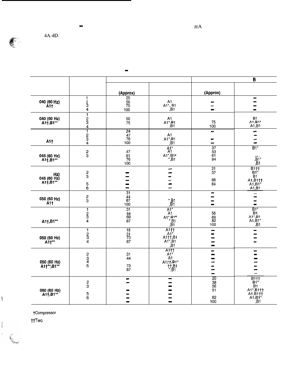
Capacity Control
The control system cycles
compressor to give capacity control steps as shown in
Tables
The unit controls leaving chilled water tem-
perature. Entering water temperature is used by the micro-
processor in determining the optimum time to add or sub-
tract steps of capacity, but is not a control set point.
The chilled water temperature set point can be automat-
ically reset by the return temperature reset or space and out-
door air temperature reset features. It can also be reset from
an external 4-20
signal with a loop isolator, or from a
network signal.
The operating sequences shown are some of many pos-
sible loading sequences for the control of the leaving water
temperature. If a circuit has more unloaders than another,
that circuit will always be the lead circuit.
Table
4A
Capacity
Control Steps, 040-070
Compressors
LOADING SEQUENCE
%
Displacement
2 5
5 0
Bl*
,
4
Al
5
Al ,Bl
1 0 0
1
040 (50
5 3
4
,
1 0 0
045 (50 Hz)
1
A l *
Al
Al
4
Al
A l & *
Al
Al
UNIT
3 0 G N
,
040 (60 Hz)
045 (60 Hz)
040 (50 Hz)
CONTROL
STEPS
1
LOADING SEQUENCE A
%
Displacement
Compressors
A l *
Al
2 5
A l *
1 0 0
Al
A l ”
Al
2 4
045 (50 Hz)
3 8
050 (60 Hz)
Al
5
1 0 0
Al
045 (50 Hz)
5
1 0 0
Al
1
1 8
045 (50 Hz)
5 6
Al
6
Al
7
1 0 0
Al ,Bl
1
045 (50 Hz)
4
6 4
7
*
Al
Al
*Unloaded compressor.
unloader, standard.
**Compressor unloader, accessory.
unloaders, both unloaded.
5