Alarm codes – Carrier 040-420 User Manual
Page 49
Alarm Codes
Following is a detailed description of
each alarm code error and possible cause. Manual reset of
an alarm is accomplished by moving
STOP-CCN Switch to STOP position, then back to LO-
CAL or CCN position. See Table 14 for listing of each alarm
code.
Code 0
No alarms exist
Codes 1 8 Compressor failure
If DSIO-LV or -EXV relay module control relay feed-
back switch or signal is sensed as open during operation of
a compressor, microprocessor detects this and stops com-
pressor, energizes alarm light, and displays a code of
3, 4, 5, 6, 7, or 8 depending on the compressor. Compres-
sor locks off; to reset, use manual reset method.
If lead compressor in a circuit shuts down, the other com-
pressors in the circuit stop and lock off. Only the alarm
mode for lead compressor is displayed.
The microprocessor is also programmed to indicate com-
pressor failure if feedback terminal on DSIO-LV or -EXV
terminal strip receives voltage when compressor is not
supposed to be on.
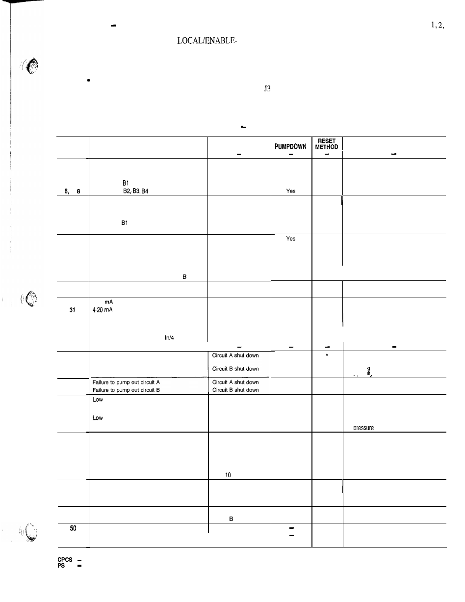
Table 14
Alarm Codes
PROBABLE CAUSE
D E S C R I P T I O N
No Alarms Exist
ACTION TAKEN
B Y C O N T R O L
C K T
N o
Compressor Al failure
Circuit A shut down
Manual
Compressor A2, A3, A4 failure
Compressor shut down
Compressor failure
Circuit B shut down
Compressor
failure
Compressor shut down
Leaving water thermistor failure
Unit shut down
Entering water thermistor failure
Unit shut down
Compressor Al sensor failure
Circuit A shut down
Compressor
sensor failure
Circuit B shut down
Reset thermistor failure
Normal set point used
Manual
Manual
Manual
A u t o
A u t o
A u t o
A u t o
A u t o
Discharge pressure transducer failure, circuit A
Circuit A shut down
Discharge pressure transducer failure, circuit B
Circuit B shut down
Suction pressure transducer failure, circuit A
Circuit A shut down
Circuit B shut down
Circuit A shut down
Auto.
A u t o
Suction pressure transducer failure, circuit B
Oil pressure transducer failure, circuit A
Oil pressure transducer failure, circuit
Circuit B shut down
Transducer supply voltage low
Unit shut down
Interlock switch oaen
Unit shut down
Yes
N o
Yes
Yes
Yes
Yes
N o
Yes
N o
N o
N o
N O
N o
N o
N o
N o
N o
A u t o
Auto.
Auto.
A u t o
A u t o
Unit voltage low or PSI faulty
M a n u a l
Chilled water pump inoperative
4-20
reset input failure
Normal set point used
demand limit failure
Demand limit ignored
Loss of communication with DSIO-LV
Unit shut down
A u t o
A u t o
Auto.
Loss of communication with DSIO-EXV
Unit shut down
Loss of communication with 4
Out module
Unit shut down
N o
Yes
N o
N o
A u t o
A u t o
Not used
I
Low refrigerant pressure circuit A
Low refrigerant pressure circuit B
Low refrigerant charge, plugged filter
drier, faulty EXV
*
Low refri erant charge, plugged filter
drier. fau tv EXV
oil pressure
circuit A
Circuit A shut down
N o
N o
N o
Manual
Faulty EXV, transducer, or thermistor
M a n u a l
Faultv EXV, transducer, or thermistor.
Manual
oil pressure
c i r c u i t B
Circuit B shut down
N o
Manual
4 2
Cooler freeze protection
Unit shut down
4 3
Low cooler water flow
Unit shut down
Low suction temperature circuit A
Low suction temperature circuit B
Circuit A shut down
after 10 minutes
Circuit B shut down
afler
minutes
N o
N o
N o
N o
Manual
Manual
M a n u a l
High suction superheat circuit A
Circuit A shut down
Manual
Low charge, faulty EXV or
thermistor, or plugged filter drier
High suction superheat circuit B
Circuit B shut down
Yes
Yes
Low suction superheat circuit A
Low suction superheat circuit B
Illegal configuration
Circuit A shut down
Circuit shut down
Unit cannot start
Initial configuration required
Unit cannot start
Emergency stop by CCN command
Unit shut down
Yes
Yes
Yes
Manual
M a n u a l
Manual
Manual
Configuration error
M a n u a l
Configuration omitted
C C N
Network command.
DISPLAY
0
1
2 , 3 , 4
5
7,
9
1 0
1 9
2 0
2 1
2 2
2 3
2 4
2 5
2 6
2 7
2 8
2 9
3 0
3 2
3 3
3 4
3 5
3 6
3 7
3 8
3 9
4 0
4 1
4 4
4 5
4 6
4 7
4 8
4 9
5 1
5 2
High-pressure switch trip, discharge gas
thermostat trip, or wiring error
CPCS Ground Fault Protection
Thermistor or transducer failure
or wiring error.
Transducer failure or wiring error
Wiring error
or improper
or faulty module
address code
Low oil level, circuit breaker trip,
faulty EXV, crankcase heater,
or Pressure Transducer
Low oil level, circuit breaker trip,
fautty EXV, crankcase heater,
or
transducer
Low water flow or faulty thermistor
Chilled water pump failure
or faulty thermistor
Faulty EXV or thermistor
Faulty EXV or thermistor
Low charge, faulty EXV or
thermistor, or plugged filter drier.
Faulty EXV or thermistor
Faultv EXV or thermistor
L E G E N D
Compressor Protection Control Module
*Reset automatic first time, manual if repeated same day
Power Supply
49