Carrier 040-420 User Manual
Page 4
In the LOCAL/ENABLE position, the chiller is under lo-
cal control and responds to the scheduling configuration and
set point data input at its own local interface device (key-
pad and display module).
In the CCN position, the chiller is under remote control
and responds only to CCN network commands. The occupied/
unoccupied conditions are defined by the network. All key-
pad and display functions can be read at the chiller regard-
less of position of the switch.
CCN run or
stop
condition is established by a command
from the CCN network. It is not possible to force outputs
from the CCN network, except that an emergency stop com-
mand shuts down the chiller immediately and causes
52” to be displayed.
Table 2
LOCAL/ENABLE-STOP-CCN
Switch Positions and Operation
S W I T C H
P O S I T I O N
STOP
LOCAL/ENABLE
U N I T
CONFIGURATION AND
OPERATION
SET POINT CONTROL
Keypad Control CCN Control
Unit Cannot Run Read/Write
Read Only
Unit Can Run
Read/Limited Write Read
Unit Cannot Run Read Only
Unit Can Run
R e a d O n l v
Read/Limited Write
Electronic Expansion Valve (EXV)
The micro-
processor controls the EXV through the EXV driver mod-
ule. Inside the expansion valve is a linear actuator stepper
motor.
The lead compressor in each circuit has a thermistor and
a pressure transducer located in the suction manifold after
the compressor motor. The thermistor measures the tem-
perature of the superheated gas entering the compressor cyl-
inders. The pressure transducer measures the refrigerant
pressure in the suction manifold. The microprocessor con-
verts the pressure reading to a saturated temperature. The
difference between the temperature of the superheated gas
and the saturation temperature is the superheat. The micro-
processor controls the position of the electronic expansion
valve stepper motor to maintain 29 F (16 C) superheat.
At initial unit start-up, the EXV position is at zero. After
that, the microprocessor keeps accurate track of the valve
position in order to use this information as input for the
other control functions. The control monitors the superheat
and the rate of change of superheat to control the position
of the valve. The valve stroke is very large, which results
in very accurate control of the superheat.
Sensors
The Flotronic
II chiller control system gath-
ers information from sensors to control the operation of the
chiller. The units
use
6 standard pressure transducers and
4 standard thermistors to monitor
pressures and tem-
peratures at various points within the chiller. Sensors are
listed in Table 3.
Table 3
Thermistor and Transducer Locations
Sensor
Sensor
D P T - A
S P T - A
O P T - A
S P T - B
O P T - B
THERMISTORS
Location
Cooler Leaving Water Temp
Cooler Entering Water Temp
Compressor Suction Gas Temp Circuit A
Compressor Suction Gas Temp Circuit B
Remote Temperature Sensor (Accessory)
Location
Compressor Al Discharge Pressure
Compressor Al Suction-Pressure
Compressor Al Oil Pressure
Compressor Bl Discharge Pressure
Compressor
Suction Pressure
Compressor
Oil Pressure
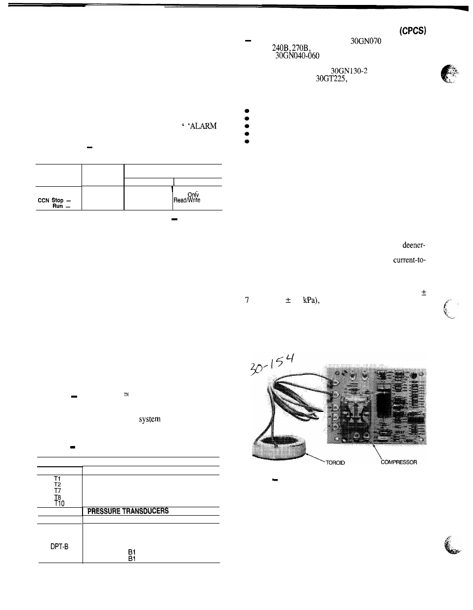
Compressor Protection Control Module
Each compressor on models
(50 Hz), 080-
100, and
has its own CPCS as standard equip-
ment. All
and 070 (60 Hz) units feature the
CPCS as an accessory, and CR (control relay) as standard
equipment. See Fig. 2. The
10 and associated
modular units and the
250, and 280 Flotronic II
units have a CR as standard equipment. The CPCS or CR is
used to control and protect the compressors and crankcase
heaters. The CPCS provides the following functions:
compressor contactor control
crankcase heater control
compressor ground current protection
status communication to processor board
high-pressure protection
The CR provides all of the same functions as the CPCS
with the exception of compressor ground current protec-
tion. Ground current protection is accomplished by using a
CGF (compressor ground fault) board in conjunction with
the CR. The CGF provides the same ground fault function
as the CPCS for units where the CPCS is not utilized.
One large relay is located on the CPCS board. This relay
(or CR) controls the crankcase heater and compressor
contactor. The CPCS also provides a set of signal contacts
that the microprocessor monitors to determine the operating
status of the compressor. If the processor board determines
that the compressor is not operating properly through the
signal contacts, it will lock the compressor off by
gizing the proper 24-v control relay on the relay board. The
CPCS board contains logic that can detect if the
ground of any compressor winding exceeds 2.5 amps. If
this condition occurs, the CPCS module shuts down the
compressor.
A high-pressure switch with a trip pressure of 426
psig (2936 48
is wired in series with the CPCS.
If this switch opens during operation, the compressor stops
and the failure is detected by the processor when the signal
contacts open. The compressor is locked off. If the lead
compressor in either circuit is shut down by the high pres-
sure switch or ground current protector, all compressors in
the circuit are locked off.
PROTECTION BOARD
Fig. 2
Compressor Protection Control Module
4