Carrier 040-420 User Manual
Page 39
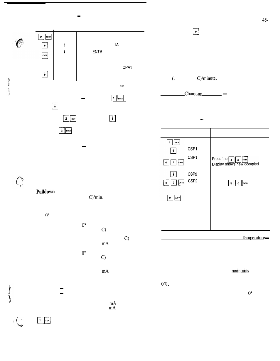
Example 3
Using Test Function
KEYPAD DISPLAY
I
ENTRY
RESPONSE
COMMENTS
C O M P
CPA OFF
CPA ON
CPA 1 OFF
CPA 2 OFF
Factory/field test of compressors
subfunction of test function
Circuit A, Compressor
test
Pressing
starts the test:
when the compressor should be running
the display shows CPA1 on
If the test is allowed to time out (10 sec-
onds) the display will show
off
Pressing the down arrow key advances
the system to Circuit A, compressor 2 test
NOTE: Once a compressor has been run using the
function, it
is not allowed to run again for 30 seconds.
E l
HISTORY FUNCTION
Keystrokes
and sub-
sequent
keystrokes display total unit run time and total
run time for each circuit.
.
Keystrokes
and subsequent
keystrokes dis-
play total unit starts and the total starts for each circuit.
Keystrokes
and subsequent
q
keystrokes dis-
play the last 5 alarms along with a description of each alarm.
SET POINT FUNCTION Set points are entered through
the keypad. Set points can be changed within the upper and
lower limits, which are fixed. The ranges are listed
below.
Chilled Water Set Point
Water:
38 to 70 F (3.3 to 21 C)
Brine:
15 to 70 F (-9.4 to 21 C)
Set Point
0.2 to 2.0 F (0.11 to 1.1
Reset Set Points
Maximum Reset Range:
to 20” F (0” to 11” C)
Maximum Reset Reference Range:
Return Fluid Reset to 20” F
(0” to 11”
External Temperature Reset 20 to 125 F
(-6.6 to 51.6
External Signal Reset 4 to 20
Minimum Reset Reference Range:
Return Fluid Reset to 20” F
(0” to 11”
External Temperature Reset 20 to 125 F
(-6.6 to 51.6 C)
External Signal Reset 4 to 20
Demand Limit Set Points
Switch Input:
Step 1
0 to 100% Capacity Reduction
Step 2
0 to 100% Capacity Reduction
External Signal:
Maximum Demand Limit 4 to 20
Minimum Demand Limit 4 to 20
Set points are grouped in subfunctions as follows:
Displays chiller water and cooling ramp set points.
a. The first value shown is the occupied chilled water
set
point.
b. The next value displayed depends on how the sched-
ule function has been programmed. (See pages
47.) If dual set point has been selected, the next set
point after
has been pressed is the unoccupied
chilled water set point. If single
set
point or inactive
schedule has been selected in the schedule function,
then when
q
is pressed, the display shows the
modified chilled water set point.
c. The final value displayed when the
q
is pressed
is the cooling ramp loading rate. This is the maxi-
mum rate at which the leaving chilled water is al-
lowed to drop, and can be field set from 0.2 to 2.0 F
11” to 1.1”
This value is not displayed
unless the function is enabled (see Adjustable Field
Configurations on page 45).
Reading and
Set Points Example 4 shows how
to read and change the chilled water set point. Other set
points can be changed by following the same procedure.
Refer to Table 9 for the sequence of display of set points in
each subfunction.
Example 4
Reading
and
Changing
Chilled Water Set Point
KEYPAD
E N T R Y
DISPLAY
RESPONSE
S E T P O I N T
44.0
420
44.0
50.0
R E S E T
C O M M E N T S
System set points
Present occupied chilled water
set point is 44 0 F
chilled water set point is 42 0 F
P r e s e n t u n o c c u p i e d c h i l l e d w a t e r
set point is 44.0 F
Press the
D
i
s
p
l
a
y
shows new unoccupied chilled
water set point is 50.0 F
Displays the maximum reset and
minimum reset set points The
minimum and maximum reference
reset set points can also be
displayed.
These set points are not
accessible when reset type has
been configured for NONE in
the service function
Temperature Reset Based on Return Water
The control system is capable of providing leaving water
temperature reset based on return water temperature. Be-
cause the temperature difference between leaving water tem-
perature and return water temperature is a measure of the
building load, return water temperature reset is essentially
an average building load reset method.
Under normal operation, the chiller
a constant
leaving water temperature approximately equal to chilled
water set point. As building load drops from 100% down to
entering cooler water temperature drops in proportion
to load. Thus, temperature drop across the cooler drops from
a typical 10 F (5.5 C) at full load to a theoretical F (0” C)
at no load. See Fig. 4.
At partial load, leaving chilled water temperature may be
lower than required. If this is allowed to increase (reset),
the efficiency of the chiller increases. Amount of reset can
be defined as a function of cooler temperature drop, as shown
in Fig. 4. This is a simple linear function that requires 4
pieces of input data for the set function:
39