Carrier 040-420 User Manual
Page 70
130 (50 Hz), 150-210, 225, 250, AND 280 UNITS (and
associated modular units)
Install control wiring. The minimum wire size for
stallation is 16
(American Wire Gage). Refer to
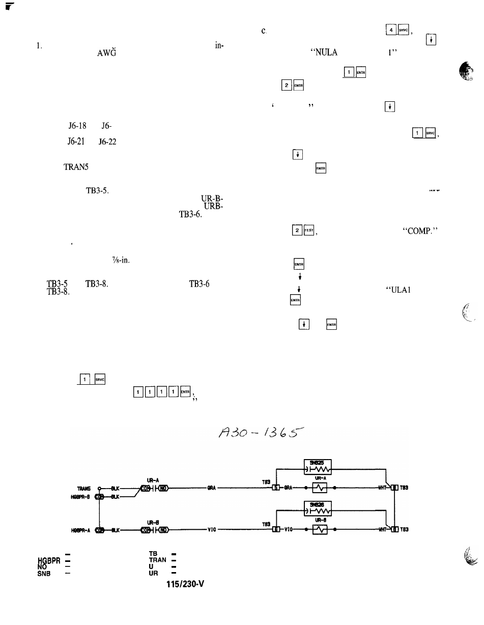
Fig. 24 and 25 for proper wiring. Open the control box
door. Locate unloader relays A and B (URA, URB) in
place of the hot gas bypass relays as shown on the com-
ponent arrangement diagram on the unit. Mount the re-
lays with the field-supplied screws. Be careful not to
damage the components and wiring in the area when mount-
ing the relays.
Wire the control side. Wire the URA coil in series be-
tween
and
19 of the 4 IN/4 OUT module with
the wires provided. Wire the URB coil in series be-
tween
and
of the same module with the wires
provided.
2
Locate the black wire in the control harness originating
from
labeled HGBPR-A-COM. Connect this wire
to the URA terminal COM. Connect the wire labeled
HGBPR-A-NO to URA-NO. Connect the wire from
URA-NO to
For an extra unloader on circuit
B,
connect the wire labeled HGBPR-B-COM to
COM, and the wire labeled HGBPR-B-NO to
NO. Connect the wire from URB-NO to
3. Wire in the solenoid valves.
NOTE: Wires external to the control box must be run in
conduit
Terminal blocks are provided for easy field wiring. Use
one of the isolated
(22-mm) holes in the side of
the compressor electrical box with a strain relief to run
the wires to the solenoid coil. Connect URA between
and
Connect URB between
and
Check all of the electrical connections for proper
location and tightness, and replace and secure the elec-
trical box of the compressor,
4. Configure the microprocessor, Once the relays are mounted
in the control box, the microprocessor must be config-
ured for the unloader option. ‘To do so:
a. Be sure the LOCAL/ENABLE-STOP-CCN switch is
in the STOP position.
b. Log into the processor and enter the service func-
t i o n u s i n g t h e k e y p a d a n d d i s p l a y m o d u l e .
Type
. The keypad LCD will display
“PASSWORD.” Enter
and the
keypad LCD will display “LOGGEDON.
COM
5
d.
To change the configuration, type
and the
keypad LCD will display “FLD CFG.” Press
until either
0” or “NULA
is displayed
(depending on the number of unloaders provided as
standard), Then press
(for 1 unloader on Al)
or
(for 2 unloaders on compressor Al). The
display will now read either “NULA 1” or
‘NULA 2, as appropriate, Press
to get to the
NULB display, and change this setting in the same
manner as with circuit A.
Once the configuration is complete, press
and the keypad LCD will display “LOGGEDON,”
Press
until the keypad LCD display reads “LOG
OFF.” Press
and the keypad LCD will display
“EXIT LOG.”
Once the unloader heads are installed, the unit is checked
for leaks, and the system is prepared for operation per
the instructions for the compressor unloader head instal-
lation, check the output of the relays using the test func-
tion as follows:
a. Press
and the display will read
b. Press the
q
to scroll down until the display reads
“CPA1 OFF.”
c. Press
, and the compressor should start.
d. Press ,
a
and the compressor should stop.
e. Press c l until the display reads
OFF.”
f. Press
, and the solenoid should energize.
g. Press
q
and the solenoid should deenergize.
h. Use the
and
keys to check the remainder of
the unloader coils.
6. Once the check has been performed, return the LOCAL/
ENABLE-STOP-CCN switch to the proper position.
7. Close and secure the control box door.
8. Start the unit and confirm that the chiller operates
properly.
LEGEND
Communications Bus
Terminal Block
Hot Gas Bypass Relay
Transformer
Normally Open
S n u b b e r
Unloader
Unloader Relay
Fig. 24 - Flotronic’” II
Unloader Wiring, 130 (50 Hz), 150-210, 225, 250, 280
7 0