Table 9 keypad directory status – Carrier 040-420 User Manual
Page 30
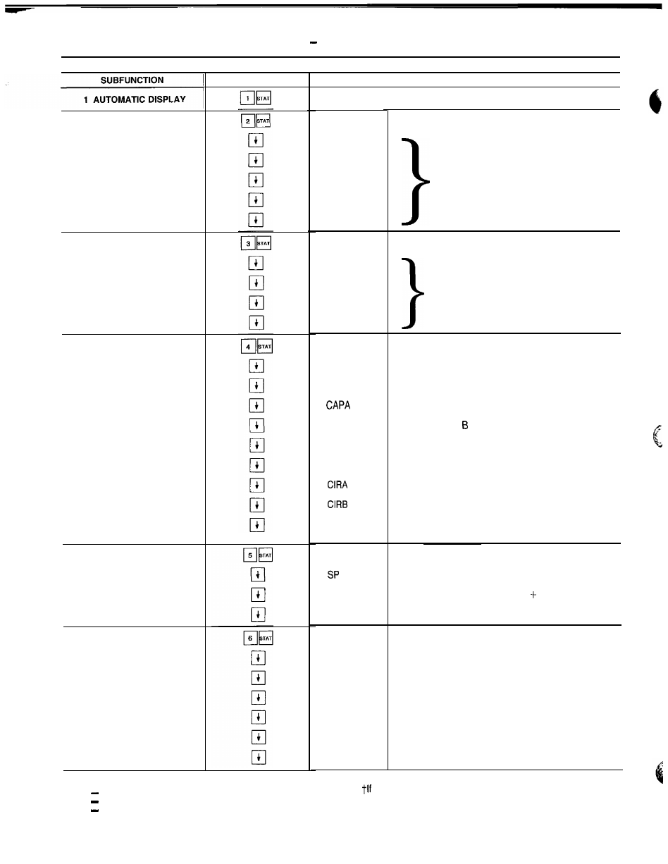
Table 9
Keypad Directory
STATUS
2 ALARMS
3 MODES
4 STAGE
5 SET POINT
6 TEMPERATURE
KEYPAD ENTRY
DISPLAY
LEGEND
CCN
Carrier Comfort Network
E X V
Electronic Expansion Valve
M O P
Maximum Operating Pressure
COMMENT
Refer to Automatic Display Operation on page 28
X A L A R M S
ALARM X
ALARM X
ALARM X
ALARM X
ALARM X
X MODES
MODE X
MODE X
MODE X
MODE X
S T A G E
S T A G E X
C A P T X
X
CAP0 X
L M T X *
LOAD X*
X
X
S M Z X
S E T P O I N T
x
M S P X
T W X
T E M P S
EWTX
L W T X
S C T A X
S S T A X
CTA X
SHA X
Number of Tripped Alarms
Displays Tripped Alarms
Number of Modes in Effect
Displays Mode in Effect
Capacity Staging Information
Number of Requested Stages
P e r c e n t o f T o t a l C a p a c i t y
Percent Circuit A Capacity
Percent Circuit Capacity
Demand Limit Set Point
L o a d L i m i t S e t P o i n t
Circuit A Compressor Relay Status
Circuit B Compressor Relay Status
Load/Unload Factor for Compressors
Factor = 1
Unloader Factor = 0 6
Fluid Set Point Information
S e t P o i n t
Modified Set Point = Set Point Reset
Cooler Leaving Fluid Temperature
Temperature Information
Cooler Entering Fluid Temperature
Cooler Leaving Fluid Temperature
Circuit A Saturated Condenser Temperature
Circuit A Saturated Suction Temperature
Compressor Al Suction Temperature
Circuit A Suction Superheat
*Must be configured
a p p l i c a b l e
3 0