R e m - - - h - - - - i, Field wiring – Carrier 040-420 User Manual
Page 71
-
-
-
-
-
-
-
-
-
-
-
-
-
-
-
I
I
-
I
-
-
-
-
-
-
-
-
-
I
I
! I
I
L
-
B
-
-
-
-
-
I
l
211
I
I
w
-
-
-
m
-
-
-
-
I
I
r
-
-
-
-
-
-
-
-
- - - -
S W I T C H
l
- - - ‘ I
I
I
I
-
-
I
-
-
-
-
-
-
-
-
-
-
-
-
-
-
-
A
-
- -
-
-
-
-
I
- - - - - - - - m - w - - - - - - -
4-20
OUTPUT
I
- - - - - I - - - - - - - - - - - - - - - - Y - -
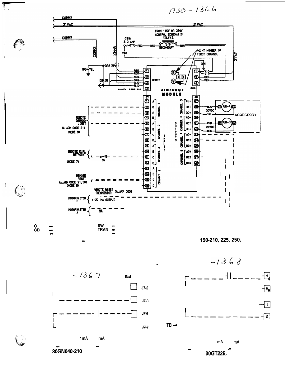
LEGEND
Contactor
Switch
Circuit Breaker
Transformer
C O M M
Communications Bus UR
Unloader Relay
Fig. 25
Accessory Unloader Control Wiring, 130 (50 Hz),
280
FIELD WIRING
Refer to Fig, 26 36 for field wiring.
4
O U T
M O D U L E
!
-
-
-
-
-
-
i
t
-
-
-
-
STAGE 1
L
STAGE2
-
-
-
-
-
-
-
- -
-
-
u
NOTE: Contacts must be rated for dry circuit application, capable of
reliably switching a 5 vdc,
to 20
load
Fig. 26A
Demand Limit
Two External Switch
Inputs,
and Associated Modular Units
T B 7
STAGE 1
L - - - - - - - - - - -
T B 7
r e m - - - H - - - -
I
T B 7
STAGE2
2
T B 7
Terminal Block
N O T E S :
1
Requires accessory options module package.
2 Contacts must be rated for dry circuit application, capable of re-
liably switching a 5 vdc,
1
to 20
load
Fig. 26B
Demand Limit
Two External Switch
Inputs,
250, 280 Units
71