Carrier Packaged Terminal s & Heat Pumps 52P User Manual
Page 47
47
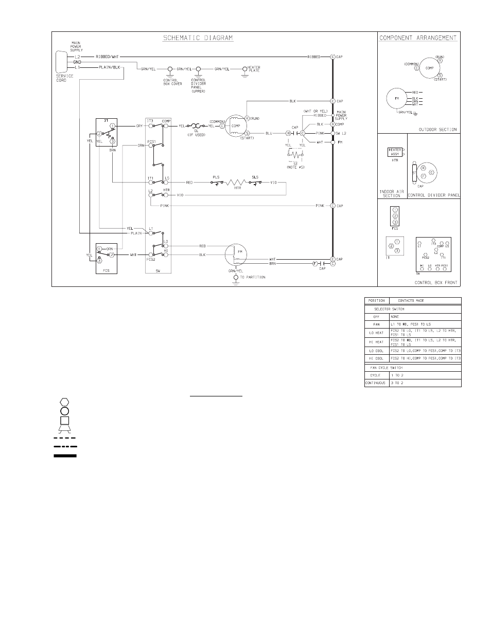
52PE and 52CE — Typical Wiring Schematic for Standard Heat/Cool Units
COMPONENT LEGEND
Component Connection (Marked)
FM
—
Fan Motor
Component Connection (Unmarked)
HTR
—
Heater
Terminal Board Connection
IT
—
Indoor Thermostat
Field Splice
NEC
—
National Electric Code
Field Control Wiring
OFT
—
Outdoor Frost Thermostat
Accessory or Optional Wiring
OL
—
Overload
To Indicate Common Potential Only Not To Represent Wire
PLS
—
Primary Limit Switch
CAP
— Capacitor
SLS
—
Secondary Limit Switch
COMP
— Compressor
ST
—
Start Thermistor
FCS
— Fan Cycle Switch
SW
—
Switch
NOTES:
1. Recommended for use on
grounded power supply only.
2. Compressor and fan motor
thermally protected.
3. Use copper conductors only.
4. All wiring must conform with
NEC and local codes.
5. Dashed lines indicate compo-
nents when used.
- 42S (72 pages)
- 30GT (4 pages)
- 48SS060 (8 pages)
- 50ME (54 pages)
- 38AH024-034 (26 pages)
- ZC (28 pages)
- 30GA (12 pages)
- COMFORTLINK 48A2 (8 pages)
- 48HE003---006 (64 pages)
- 33ZCSECTRM (52 pages)
- 19XRV (40 pages)
- MODU-PAC 50DF (37 pages)
- 17DA (8 pages)
- SINGLE PACKAGED ELECTRIC COOLING UNITS 50GS (28 pages)
- 48JZ (N) 024-060 (30 pages)
- 30GX080-176 (8 pages)
- 50DL (24 pages)
- 50GL-A (4 pages)
- NP034-074 (72 pages)
- 40GXQ (12 pages)
- 30XA080-500 (8 pages)
- 39E (12 pages)
- 40KMQ------301 (10 pages)
- 38AE (12 pages)
- 48AW (118 pages)
- 38GXQ (28 pages)
- 48ES---A (38 pages)
- 48GL (22 pages)
- 48GH (22 pages)
- 40QA024-060 (24 pages)
- TJF004 (52 pages)
- 39LD (40 pages)
- 48DL (4 pages)
- 48/50TC04---28 (44 pages)
- 50EJ (56 pages)
- 17EX (120 pages)
- 50BA (24 pages)
- 50BB (16 pages)
- 50BB (8 pages)
- 50BJ (20 pages)
- 30H (16 pages)
- 48HJD005-007 (48 pages)
- 50ZP (6 pages)
- 50DP016 (16 pages)
- 50LJ008-014 (19 pages)