Product features and benefits (cont), Easy access to chassis, Hidden controls – Carrier Packaged Terminal s & Heat Pumps 52P User Manual
Page 10: Temperature limiter and control knob, Outdoor air vent control, Fan cycle switch, The vent will provide 50 cfm of fresh air
10
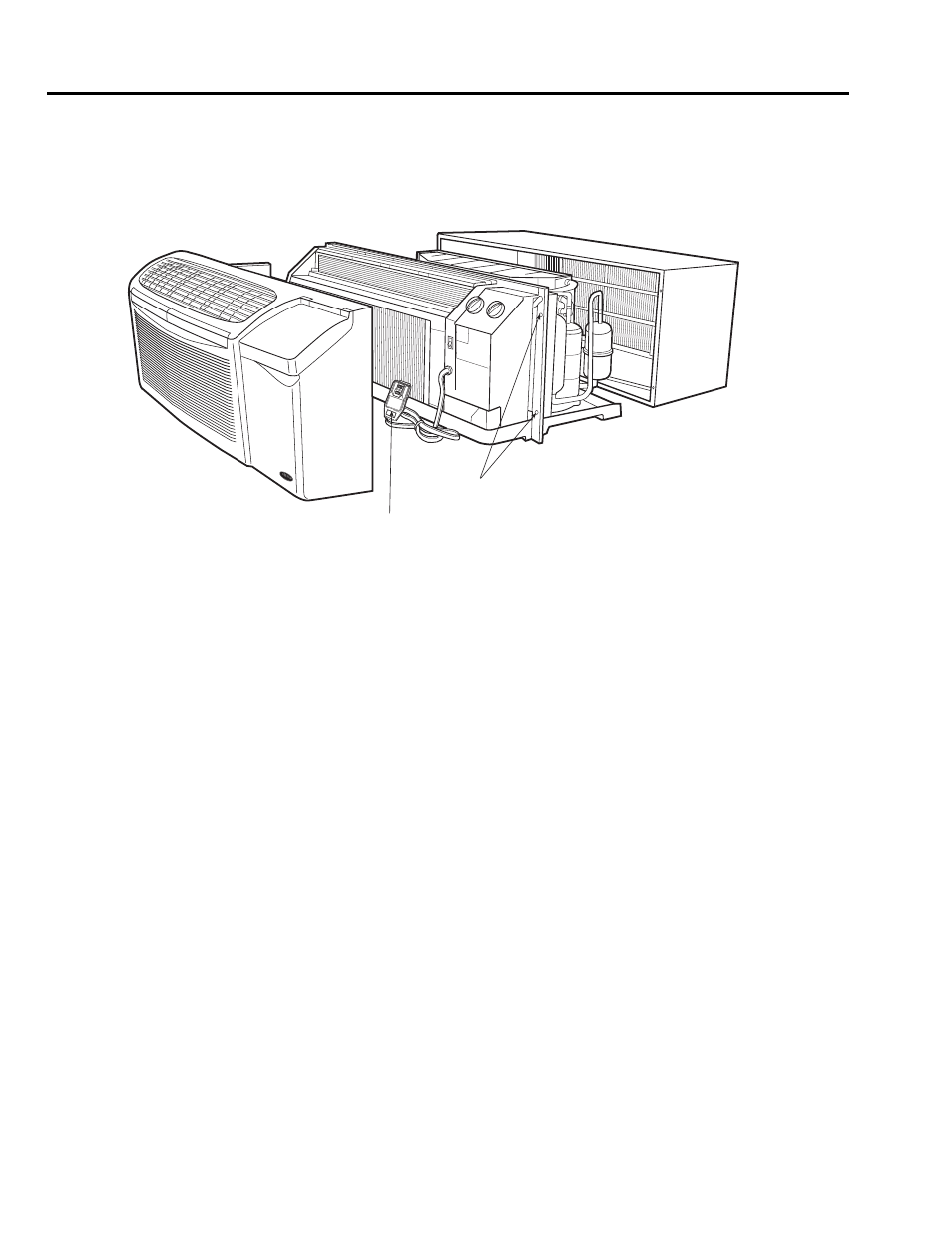
EASY ACCESS TO CHASSIS
Access to the chassis simply requires removing four
screws and then sliding the chassis out of the sleeve
for service.
HIDDEN CONTROLS
The factory-wired control box houses all control com-
ponents and is quickly accessible without removing
the chassis from the wall sleeve. By simply removing
two screws on control box, the hinged door lowers,
providing quick access to all the electrical compo-
nents. The wiring diagram is located on the front of the
control box door.
Temperature Limiter and Control
Knob
The limiter reduces operating costs by allowing the
owner to control the range of cooling and heating tem-
peratures available to the occupant. It is located under
the front panel on control box, out of the occupant’s
sight. Each setting on the limiter is equivalent to 5° F
and the range of temperature settings available to the
owner is from 60 to 90 F. The limiter is not pre-set at
the factory (providing full range for the occupant).
Outdoor Air Vent Control
Control of the outdoor-air vent is handled by a vent
handle located under the front panel on the left side of
the unit. This handle rotates to manually open and
close the outdoor vent.
The vent will provide 50 cfm of fresh air.
NOTE: If more fresh air cfm is required, a Power-Vent
Kit is available (see accessories).
Fan Cycle Switch
The fan cycle switch allows the fan to operate in
2 modes:
• Continuous — This setting allows the fan to run
continuously, circulating air even when the temper-
ature setting has been satisfied. This setting, which
helps to keep the room temperature closer to the
thermostat setting, is used for maximum comfort.
• Cycle — This setting allows the fan to cycle on and
off with the compressor during heating or cooling.
The fan stops when the temperature setting is
reached. The longer unit off-time makes this option
more energy-efficient with only slightly wider vari-
ations in room temperature.
NOTE: On wall thermostat models, the fan cycle/
continuous feature is typically located at the wall
thermostat.
PRODUCT FEATURES AND BENEFITS (cont)
CHASSIS ATTACHMENT SCREWS
(SAME LOCATION ON OPPOSITE SIDE)
1.PR
ESS
RES
ET B
UTTO
N.
2.PLU
G IN
TO P
OW
ER
RE
CEP
TAC
LE.
3.PR
ESS
TES
T BU
TTO
N UN
IT
SH
OULD
LIG
HT.
4. PR
ESS
RES
ET B
UTTO
N AG
AIN
FO
R US
E.
TESTING
DO N
OT U
SE IS
TES
T AB
OVE
FAIL
S
PLUG TEST/
RESET BUTTONS
Easy Service Access