52p and 52c with subbase – Carrier Packaged Terminal s & Heat Pumps 52P User Manual
Page 32
32
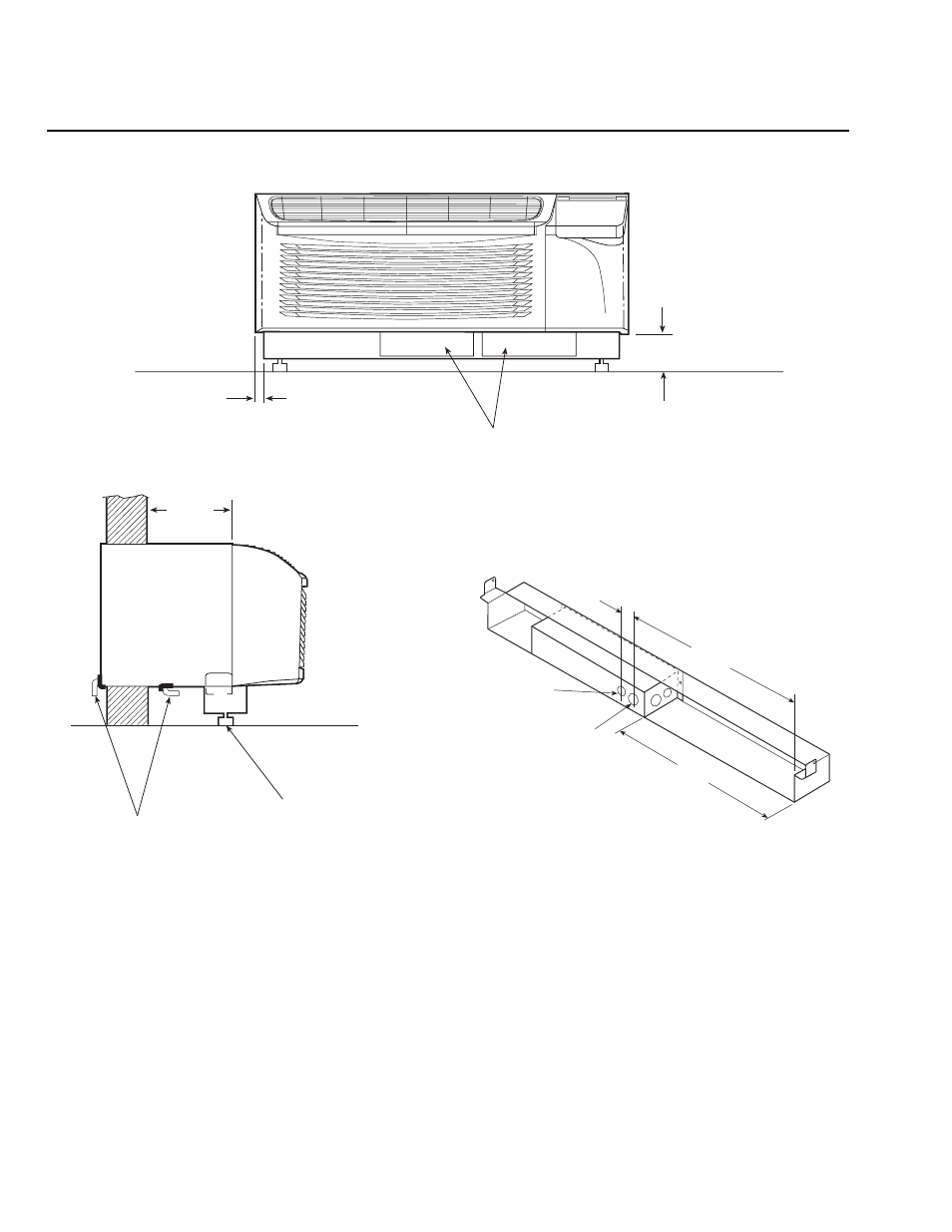
52P AND 52C WITH SUBBASE
0’-0 7/8”
(22)
SUBBASE ACCESS COVERS
0’-3 1/4” MIN. (83)
0’-5 1/2” MAX. (140)
OUTSIDE
WALL
SIDE
SUBBASE LEVELING BOLTS
ACCESSORY DRAIN
(EXTERNAL OR INTERNAL)
SEE
NOTES
(3) 1 1/8” (28.6) DIA.
KNOCKOUTS
19 1/2”
(495.3)
17”
(431.8)
1 9/16”
(39.7)
(3) 7/8” (22.2)
DIA. KNOCKOUTS
REAR VIEW
ACCESSORY SUBBASE
ELECTRICAL CONNECTIONS
NOTES:
1. Accessory subbase is required for applications where:
• Wall sleeve extends 4 or more inches into the room.
• Wall thickness is less than 2 inches.
• All 265-v cord-connected applications.
2. For all applications with an accessory subbase:
• Wall sleeve must extend 4 in. minimum into the room and 3
1
/
4
in. minimum above the floor.
• Subbase height is adjustable from 3
1
/
4
in. minimum to 5
1
/
2
in. maximum above floor (including carpeting).
Refer to wall sleeve installation instructions.
DIMENSION DRAWINGS AND INSTALLATION
DATA — NEW CONSTRUCTION (cont)
- 42S (72 pages)
- 30GT (4 pages)
- 48SS060 (8 pages)
- 50ME (54 pages)
- 38AH024-034 (26 pages)
- ZC (28 pages)
- 30GA (12 pages)
- COMFORTLINK 48A2 (8 pages)
- 48HE003---006 (64 pages)
- 33ZCSECTRM (52 pages)
- 19XRV (40 pages)
- MODU-PAC 50DF (37 pages)
- 17DA (8 pages)
- SINGLE PACKAGED ELECTRIC COOLING UNITS 50GS (28 pages)
- 48JZ (N) 024-060 (30 pages)
- 30GX080-176 (8 pages)
- 50DL (24 pages)
- 50GL-A (4 pages)
- NP034-074 (72 pages)
- 40GXQ (12 pages)
- 30XA080-500 (8 pages)
- 39E (12 pages)
- 40KMQ------301 (10 pages)
- 38AE (12 pages)
- 48AW (118 pages)
- 38GXQ (28 pages)
- 48ES---A (38 pages)
- 48GH (22 pages)
- 48GL (22 pages)
- 40QA024-060 (24 pages)
- TJF004 (52 pages)
- 39LD (40 pages)
- 48DL (4 pages)
- 48/50TC04---28 (44 pages)
- 50EJ (56 pages)
- 17EX (120 pages)
- 50BB (16 pages)
- 50BB (8 pages)
- 50BA (24 pages)
- 50BJ (20 pages)
- 30H (16 pages)
- 48HJD005-007 (48 pages)
- 50ZP (6 pages)
- 50DP016 (16 pages)
- 50LJ008-014 (19 pages)