Typical wall installation, 52p and 52c dimension drawing – Carrier Packaged Terminal s & Heat Pumps 52P User Manual
Page 27
27
TYPICAL WALL
INSTALLATION
Proper building practices must be used when con-
structing a wall opening to support a PTAC wall sleeve
and chassis.
If practices are unknown, consult your local architect
or building contractor.
Installed wall sleeve must be level from side to side
and front to back.
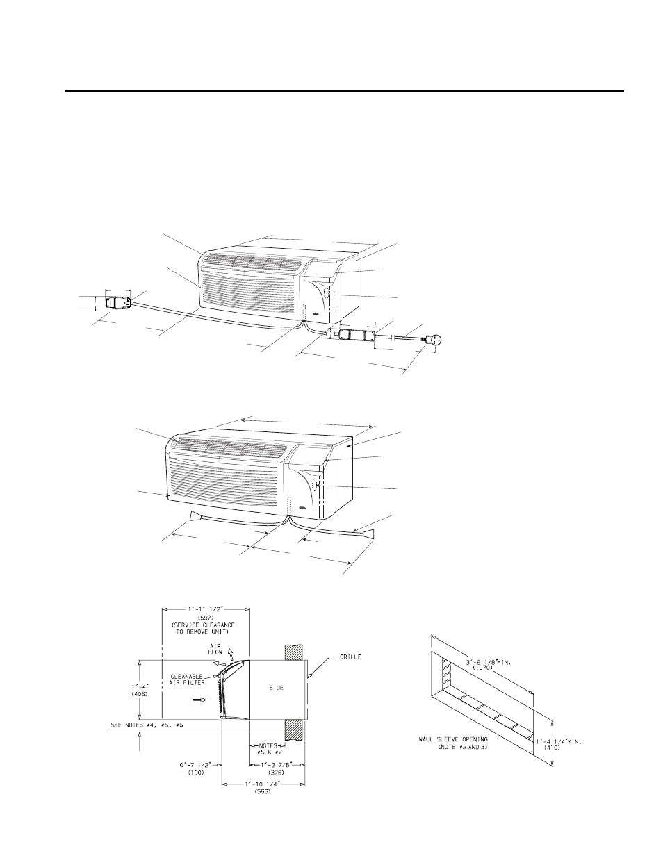
DIMENSION DRAWINGS AND INSTALLATION
DATA — NEW CONSTRUCTION
DISCHARGE
GRILLE
REMOVABLE
FRONT PANEL
1 -10
(558.8)
6
(152.4)
4 -4
(1320.8)
3 -6
(1067)
HINGED CONTROL
ACCESS DOOR
(SEE NOTE #8)
ACCESSORY
WALL SLEEVE
208/230-V
SERVICE CORD
15/20 AMP
PLUG HEAD
2.03"
(51.6)
3.94"
(100)
7.24"
(184)
12"
(304.8)
30 AMP
2.00"
(50.7)
30 AMP IN-LINE
CORD
REMOVABLE
FRONT PANEL
6”
(152.4)
3’-6”
(1067)
HINGED CONTROL
ACCESS DOOR
(SEE NOTE #8)
15”
(381)
15”
(381)
ACCESSORY
WALL SLEEVE
265-V
SERVICE CORD
(SEE NOTE #9)
DISCHARGE
GRILLE
52P and 52C Dimension Drawing
NOTES:
1. Dimensions in parenthesis are in
millimeters.
2. Minimum opening sizes apply to
all wall openings.
3. Proper building practices must
be used when constructing a
wall opening to support a PTAC
wall sleeve and chassis. If prac-
tices are unknown, consult your
local architect or building
contractor.
4. Installed wall sleeve must be
level from side to side and front
to back (do not use rails to level
sleeve).
5. If wall sleeve extends into the
room more than 4 in., an acces-
sory subbase or field fabricated
front support should be used to
prevent wall sleeve from tipping
forward.
6. For all applications with an
accessory subbase, wall sleeve
must extend into room 3
1
/
4
-in.
(83 mm) minimum and 3
1
/
4
-in.
(83 mm) minimum from floor.
7. For all applications with an
accessory lateral duct, sleeve
must extend into the room 3-in.
(76.2 mm) minimum. In applica-
tions where the sleeve will not
extend a minimum 3-in., the lat-
eral duct mounting brackets
must be mounted on the
wall sleeve prior to wall sleeve
installation.
8. Remote control models, “RC”
and “RP” units, use low voltage
connections (24-volt AC).
9. 265-volt cord connected units
must plug into a 265 volt electri-
cal subbase per UL requirement
(or hardwire can be used).
10. The 265-volt electrical cord is
approximately 15-in. long from
where it exits the front panel.
208/230-V UNITS
265-V UNITS