Rally Armor 08-11 Subaru Impreza & 08-10 WRX User Manual
Page 3
Start: Place t
below). Align cl
right next
to th
using all mount
adjustment (Fig
TIP #5:
You ca
placed right next
TIP #6:
To avo
clamp will embed
TIP #7
: The st
spraying addition
and assist in reinf
TIP #8:
An offs
the rear portion o
Option #2
Rear
Although an ad
for lowered/tra
point inside the
In summary, yo
1. Bolting the m
2. Raising and s
3. Placing the h
4. Marking the
5. Drilling a sma
6. Bolting the s
Start: Mount t
to your vehicle
vehicle/ground
TIP #9:
While
two polygon clips (It
lamp (Item RRCLMPW
e red outlined portio
ting points and
short
gure “N” below). Wh
n place the mud flap tem
to first indentation in th
id hitting the clamp dire
d itself into undercoating
eel clamp is the only no
al undercoating spray ov
forcing the area when fu
fset or ratcheting screwd
of the vehicle up and allo
The hardw
r Mud Flap Installati
dditional step in the m
ack/rally and extrem
e rear wheel well of t
ou will be:
mud flap on the rear
securing the vehicle,
hardware on the on r
appropriate pilot‐ho
aller than the screw
crew through the ne
he rear flap utilizing
via the short screw/
d, and tighten bolts u
drilling the pilot point fo
em PolCl) over the tw
WRX) with clip facing
on (see Figure “M” b
t screws
(utilize lowe
hen correctly adjuste
mporarily against the bu
he wheel well.
ectly, it is recommended
g & body of the vehicle.
on stainless component o
ver /on the clamp & are
ully dried (usually about
driver is recommended a
ow the rear tire to drop t
ware is very strong a
on‐ More Secure me
mounting process, th
e conditions. The mu
the vehicle.
bumper by utilizing t
and removing tire/w
rear upper mounting
ole area.
pilot‐hole on the ma
ew pilot hole created
the two outer moun
/washer combination
ntil snug.
or mounting point,
conf
wo outer mounting h
g forwards right next
elow) and hammer w
er
inner
rear mountin
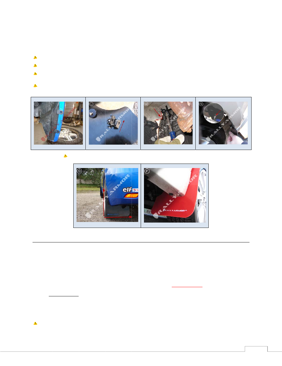
d, (Figure “O” below
umper to familiarize you
d that a flat head screwd
of your hardware and ha
ea surrounding is recomm
15 minutes to touch). T
as it allows you to compl
to ease access without t
and self threading bu
ethod
his option is recomm
ud flaps feature an a
the two outer holes,
wheel.
g point, bolting mud f
ark you created.
d with all the hardwa
nting points on the ve
n. (See Figures “K” an
firm that the area oppos
holes (Figure “K” belo
t to the visible indent
with a mallet upward
ng point on flap for th
w) fully tighten down
urself with the mounting
driver be placed within t
as been coated with a ru
mended before complet
The spray is readily availa
lete the installation with
tire removal.
ut over‐tightening the
ended as more of
se
dditional rear “uppe
aligning the mud fla
flap using two outer
re completing the in
ehicle by placing the
nd “N” in Clamp met
site to where you are cre
ow). Place polygon c
tation on the body (t
ds
until flush
with bo
he clamp), until wash
all 3 bolts to comple
point
before
installing t
the clamp and the handl
ust resistant coating fro
ting the installation. Th
able in most auto parts
h the narrow clearance b
e clips beyond their l
ecure way to mount
r” mounting point th
ap so that it is exactly
holes and
properly a
stallation.
polygon clips over t
hod above). You mus
eating the point is clear
clip over mounting ar
the arm swivels shou
ody (see tip #5, #6 an
her meets the flap, b
ete installation (Figur
the clamp. Your flap is d
le is used as the striking
m our facility. To help p
is extra step helps to pro
stores and can also be a
between the tire and the
limit is not recomme
your rear flap on the
hat will allow you to
y perpendicular to th
aligning it first
.
he rear bumper mou
st
align flap until per
and in the tabbed area
rm as shown (Figure
uld you require). Plac
nd #7). Bolt the mud
but allows for slight
re “P” below).
designed to mount prope
point. After hammering
revent potential surface
otect the surface of the
added after the installat
e body. Alternatively, you
ended.
e vehicle. This is mo
mark and drill a mou
he vehicle and ground
unting holes, and mo
rpendicular to the
projecting out of the ve
3
“L”
ce clamp
flap up
erly when
g, the
e rust,
clamp
ion as well
u can jack
st useful
unting
d.
ounting
ehicle