Rally Armor 08-13 Mitsubishi EVO X User Manual
Rally Armor For bicycles
Rally Armor
2008+ Mitsubishi Lancer Evolution X
Mud Flap Mounting Instructions
Please read the instructions thoroughly before attempting to install mud flaps. Rally Armor always recommends professional installation.
For high resolution images and the most up to date instructions please visit our mounting instructions area on http://www.rallyarmor.com
To protect and extend the life of your rally mud flap set care must be taken during parking and reversing.
Your mud flap set contains 4 flaps total for all four tires of the vehicle. Front flaps (4 mounting holes) – Rear flaps (3 mounting holes).
Your mounting hardware has been checked at our facilities. It consists of:
Quantity
Hardware Item
Item ID
12
Polygon Edge Clips
PolCl
16
Washers
Wash
8
Short Stainless Steel Screws
1SS
8
Long Stainless Steel Screws
1.5SS
2
Plastic Inserts (fender liner)
Ins
2
Plastic Inserts (bracket)
Ins2
2
“L” Brackets (rear flaps)
Lbrkt
2
Short “L” Brackets (front flaps)
Lbrkt2
1
Recommended Tools: Short Phillips Screwdriver; Offset/Ratcheting Phillips; Flat head Screwdriver; Marker; Metal Pick
Front Mud Flap Installation
1. Begin by parking the vehicle on an even surface. Turn the steering wheel towards the side you are working on to gain access to the wheel
well area.
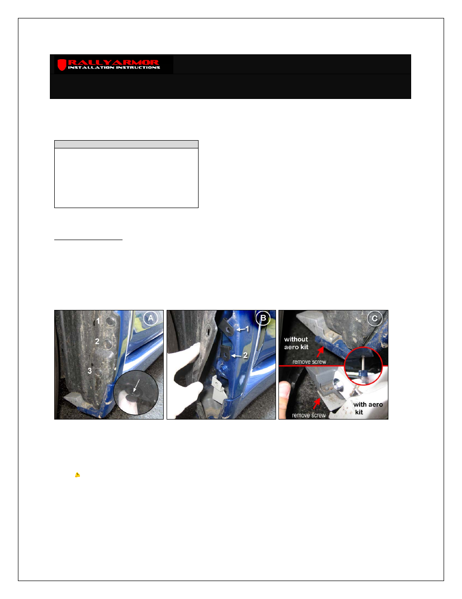
2. Remove the 3 wheel well fasteners (#1‐3) that secure the fender liner to the vehicle. To remove the fasteners, pop the inner tab out of the
assembly first then remove the complete assembly by prying the outer edges of the fastener (Figure A).
3. Pull fender liner away from the body of the vehicle and position 2 polygon clips (PolCl), as shown, over mounting points 1 and 2 (Figure B).
Reinstall liner over the clips.
4. From under the vehicle remove the factory screw temporarily; this screw will be reinstalled. The factory screw connects the front inner side
skirt area to the body of the vehicle (Figure C).
5. Place insert for bracket (Ins2) flush into larger hole A of the short L mounting bracket. Slide bracket into side skirt area and align hole B to
corresponding hole on the side skirt (Figure D).
6. Secure the bracket to the vehicle in the area where the factory screw was removed to hole B on the bracket. Remount factory screw
previously removed and leave slightly loose for adjustment. Position assembled bracket as pictured (Figure E).
7. Match front mud flap against the vehicle mounting points (#1‐3) with logo facing the rear of the vehicle. Place a long (1.5SS) screw through a
washer (Wash) and loosely thread mounting points #1 and #2. Step away from the vehicle and adjust mud flap until perpendicular to the
ground.
Tip: On non‐Aero kit EVOs slide bracket behind stock skirt lip.
8. With a marker mark the center of mounting hole #4 (Figure F). Remove mud flap.