Palm rest assembly, Removing the palm rest assembly – Dell Latitude E4200 (Late 2008) User Manual
Page 38
Back to Contents Page
Palm Rest Assembly
Dell™ Latitude™ E4200 Service Manual
Removing the Palm Rest Assembly
Replacing the Palm Rest Assembly
Removing the Palm Rest Assembly
1.
Follow the instructions in
Before Working on Your Computer
.
2.
Remove the service panel (see
Removing the Service Panel
).
3.
Remove the WLAN and WWAN cards (see
Removing the WLAN/WiMax Card
and
Removing a WWAN Card
).
4.
Remove the memory module (see
Removing the Memory Module
).
5.
Remove the solid state drive (see
Removing the Solid State Drive and Cable Assembly
).
6.
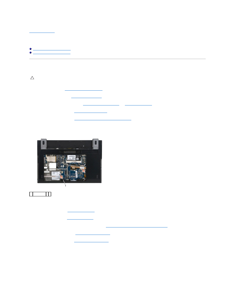
Disconnect the fingerprint reader/wireless switch cable from the system board by gently pulling on the connector release.
7.
Remove the two silver M2 x 5-mm screws labeled "P".
8.
Turn the computer topside up.
9.
Remove the LED cover (see
Removing the LED Cover
).
10.
Remove the keyboard (see
Removing the Keyboard
).
11.
Remove the module with Bluetooth
®
wireless technology (see
Removing the Card With Bluetooth Wireless Technology
).
12.
Remove the display assembly (see
Removing the Display Assembly
).
13.
Remove the coin-cell battery (see
Removing the Coin-Cell Battery
).
14.
Disconnect the ExpressCard and touch pad cables from the system board by gently lifting up on the latches near the cable connectors.
CAUTION:
Before working inside your computer, read the safety information that shipped with your computer. For additional safety best
practices information, see the Regulatory Compliance Homepage on www.dell.com at: www.dell.com/regulatory_compliance.
1 screws (2)