System memory, Replace the daughter card if it was removed. see, Installing a daughter card – Dell PowerVault 745N User Manual
Page 61
Installing a Daughter Card
1.
Open the system. See "
Opening the System
" in Troubleshooting Your System."
2.
Connect the LED cable to the connector on the bottom of the daughter card. See
.
3.
Use the #2 Phillips screws to secure the daughter card to the system board.
4.
Insert the daughter card firmly into the connector on the system board until the card is fully seated.
5.
Connect the hard-drive cables to the connectors on the daughter card.
Ensure that port 0 of the daughter card is connected to the cable for hard drive 0, port 1 is connected to the cable for hard drive 1, and so forth.
6.
Close the system. See "
Closing the System
" in "Troubleshooting Your System."
System Memory
The four memory module sockets are located on the system board adjacent to the power supply and can accommodate from 512 MB to 4 GB of unbuffered ECC
P C-3200 (DDR400) memory. See
for the location of the memory module sockets.
You can upgrade the system memory by installing combinations of 256-, 512-MB, and 1-GB unbuffered memory modules. If you receive an error message
stating that maximum memory has been exceeded, see "
Indicators, Messages, and Codes
" for more information. You can purchase memory upgrade kits from
Dell.
Memory Module Installation Guidelines
The memory module sockets are arranged in banks (1 and 2) on two channels (A and B). See
Figure A
-3
for the location of the memory module sockets. The
memory module banks must be installed in identical pairs.
The memory module banks are identified as follows:
l
Bank 1: DIMM1_A and DIMM1_B
l
Bank 2: DIMM2_A and DIMM2_B
For example, if socket DIMM1_A contains a 256-MB memory module, then socket DIMM1_B must contain a 256-MB memory module.
shows examples of different memory configurations.
l
If only one memory module is installed, it must be installed in the DIMM1_A socket.
l
A bank must contain identical memory modules.
l
Install the memory modules in bank 1 (DIMM1_x) before installing memory modules in bank 2 (DIMM2_x).
l
Installing three memory modules is not supported.
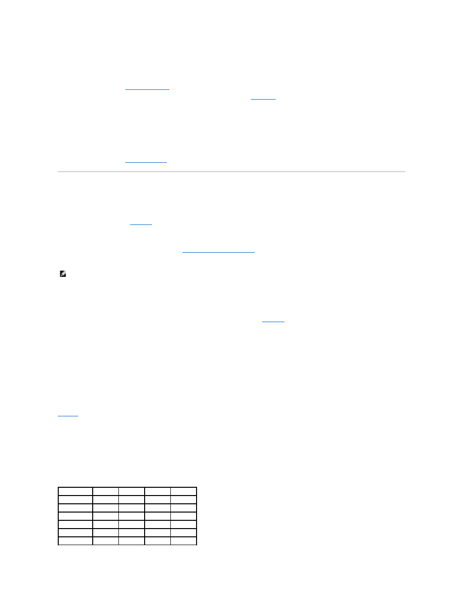
Table 6-1. Sample Memory Module Configurations
NOTE:
The memory modules must be PC-3200 compliant.
Total Memory DIMM1_A DIMM2_A DIMM1_B DIMM2_B
512 MB
256 MB
None
256 MB
None
1 GB
256 MB
256 MB
256 MB
256 MB
1 GB
512 MB
None
512 MB
None
1.5 GB
512 MB
256 MB
512 MB
256 MB
2 GB
1 GB
None
1 GB
None
2 GB
512 MB
512 MB
512 MB
512 MB