Back-panel indicators and features, Table 2 – Dell PowerVault 745N User Manual
Page 27
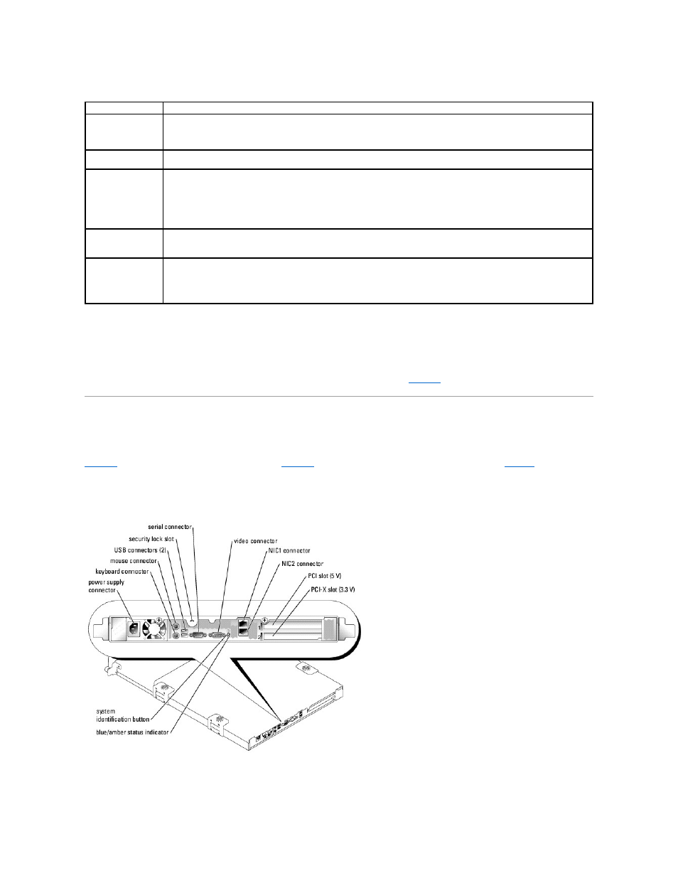
Table 2-1. Front-Panel Indicator Codes
l
The power button provides the ability to soft switch the power cycling to the system.
l
The two system identification buttons on the front and back panels can be used to locate a particular system within a rack. When one of these buttons
is pushed or the system management software is used to identify the system, the blue system status indicators on the front and back of the system
blink. (To stop the indicator from blinking press one of the identification buttons a second time, or use the systems management software.)
The front panel also incorporates a USB connector that is accessible when the bezel is removed. See
.
Back-Panel Indicators and Features
shows the back-panel indicators and features and
shows the indicators for the integrated network adapters.
conditions associated with each back-panel indicator code.
Figure 2-2. Back-Panel Features
Figure 2-3. Network Adapter Indicators
LED Indicator
Description
Blue/amber system
status indicator
The blue system status indicator lights up during normal system operation or when you press the system identification button. You
can also use the systems management software to cause this indicator to flash to identify a particular system.
The amber system status indicator flashes when the system needs attention due to a possible system problem.
Hard-drive activity
indicator
The green hard-drive activity indicator flashes when the hard drives are in use.
Hard-drive status
indicator
The green hard-drive status indicator lights up when the drive is ready and is functioning normally. The status indicator is off when
the drive is absent and is not configured as part of a RAID or non-RAID volume or cannot be detected by the operating system or
RAID controller.
The green status indicator blinks when a volume of which the drive is a member is rebuilding.
The amber status indicator blinks when a fault occurs with the drive.
NIC1 and NIC2 link
indicators
The indicators for the two integrated network adapters light green if the network adapters are connected to the network.
The indicators flash green when data is being transmitted.
Power indicator
The green indicator flashes if AC power is available to the system, but the system is not powered on.
The green indicator is on when the system is powered on.
If the system is not connected to AC power, the green indicator is off.