Two-switch sample topology, Two-switch sample topology -4, Figure 2-2 – Dell PowerVault 51F (8P Fibre Channel Switch) User Manual
Page 50
2-4
Dell PowerVault 51F 8-Port Fibre Channel Switch Installation and Troubleshooting Guide
DELL CONFIDENTIAL - Preliminary 4/6/00
FILE LOCATION: S:\SYSTEMS\Boxer\rev_i&t\English\50UWDa00\50UWDc20.fm
Figure 2-1 shows the switch’s F_Ports and FL_Ports and the corresponding N_Port
and NL_Port connections on the device side. The switch connections are shown as
they would be in a physical installation. Functionally, the switch becomes a fabric with
every device connected to every other device by the fabric.
Each connection is full duplex with transmissions up to 1 Gbps bandwidth simulta-
neously, in both directions, between the fabric and fabric-connected devices.
Two-Switch Sample Topology
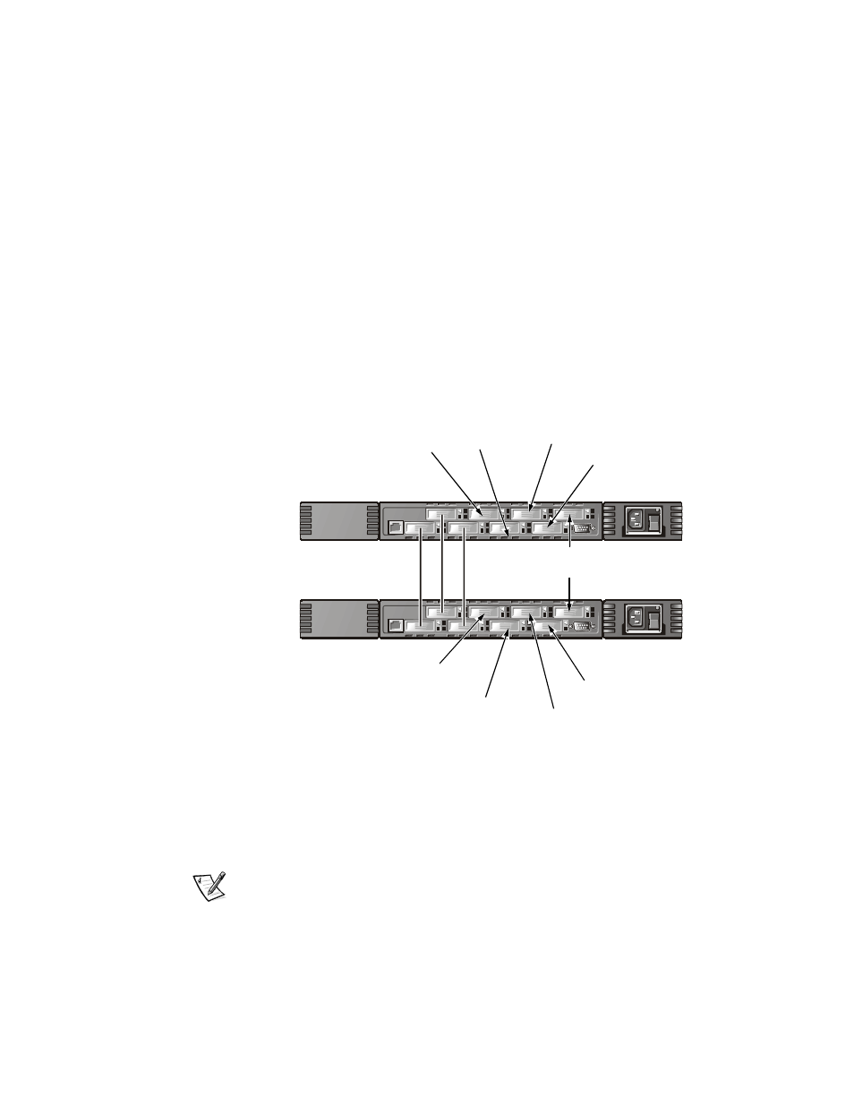
The two-switch topology increases the number of connectivities and aggregate fabric
bandwidth, as shown schematically in Figure 2-2. The switches are shown physically
connected although the connections are transparent in the fabric. Functionally, the
devices appear to be connected together directly.
Figure 2-2. Fabric Topology Sample With Three Connections
Between Two Switches
When a fabric is initiated, or when a new switch is added to the fabric, the switches
determine a least-cost path for each destination switch. This is done dynamically each
time the fabric configuration changes and the results are stored in the switch’s inter-
nal routing tables.
NOTE: After a path has been determined, it is not rerouted, even though traffic vol-
ume may change over time, for each path to maintain in-order delivery. If the link fails,
the path is rerouted.
Switch A
Switch B
E_Port
E_Port
RAID A
RAID B
HOST3
HOST4
HOST1
HOST2
RAID A
RAID B
JBOD A
HOST5