Fig 4.14 drag-link and rrf position – B&G H2000 Pilot *DISCONTINUED* User Manual
Page 96
h2000 Autopilot User Manual
Part 4 - Installation Information
HB-0842-04
4-18
If the maximum rudder angle is less than 90º then the position of
the RRF or the drag-link must be adjusted so that the operating
arm of the RRF swings through a minimum of 90º and the output
voltage difference is greater than 1 volt from port to starboard lock.
Measure the output of the RRF between the green and blue wires.
Note
If there is less than 1V dc difference, the autopilot will not
commission.
1V MINIMUM
VARIATION
90° MINIMUM RRF ANGLE
RRF
Fig 4.13 RRF Position
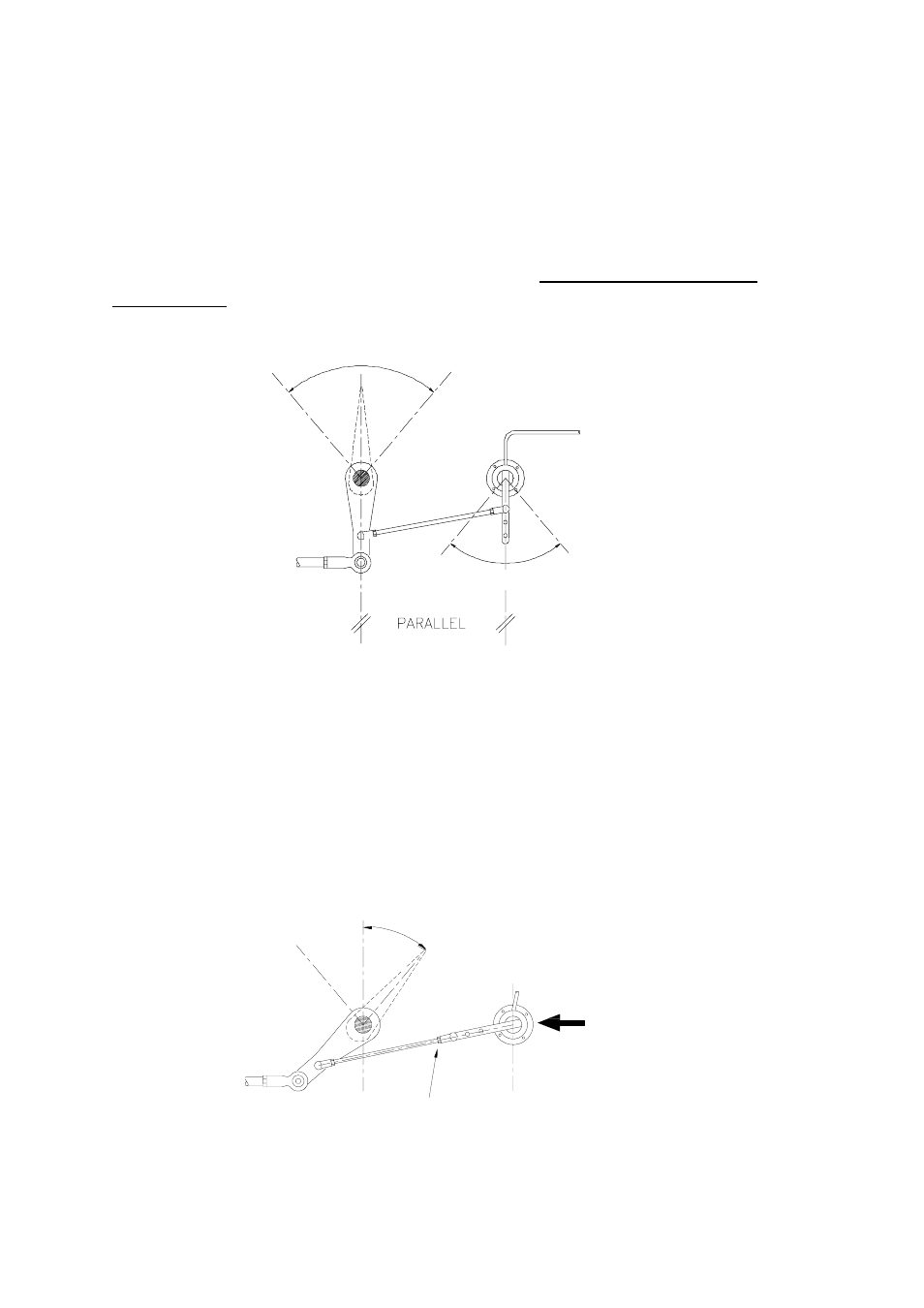
The rudder hard-over angle should only be limited by the rudder
stops and not the RRF linkage. Check that when hard-over the
RRF arm and drag-link, do not form a straight line. If this occurs,
the steering system could become damaged or jammed
endangering the boat and crew. Rectify this immediately by
adjusting the position of the RRF.
Move RRF to
Correct
Drag-Link and RRF Arm must NOT
form a straight line
Fig 4.14 Drag-Link and RRF Position