Fig 4.18 proportional solenoid connections – B&G H2000 Pilot *DISCONTINUED* User Manual
Page 101
h2000 Autopilot User Manual
Part 4 - Installation Information
HB-0842-04
4-23
4.5.4
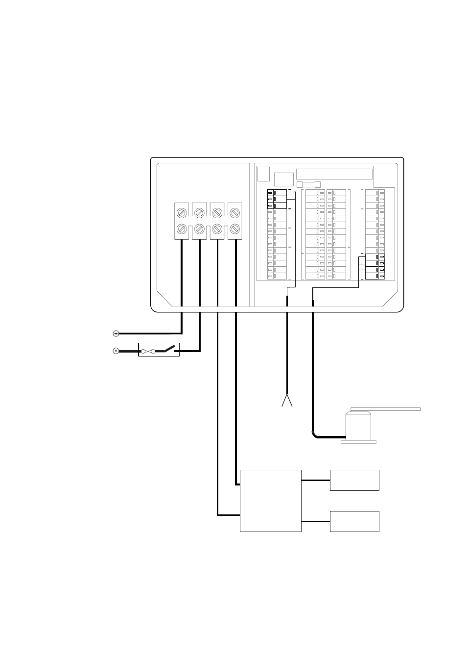
Proportional Solenoid Connections
These are general wiring instructions only, showing the connection
of the ACP Computer Unit outputs to drive proportional solenoid
valves. The continuous drive pump motor will also require a heavy-
duty supply; this is not shown on this diagram. The clutch output
could be used to control the motor supply; the clutch output is only
active while the Autopilot is moving the rudder.
DRIVE
SUPPLY
DRIVE
SUPPLY
IN
OUT
-
+
-
+
1A
BR
BL
SLV
R
BL
SLV
BL
R
SLV
R
W
BR
G
V
BL
Y
BLK
SLV
R
G
SLV
BL
R
R
BL
SLV
G
W
Y
BR
R
BLK
SLV
R
G
BL
SLV
R
BL
SLV
R
BLK
G
W
BL
Y
SLV
BLK
G
R
SLV
C
L
UT
CH
MOB
AL
ARM
PADDLE
G
Y
RO
-S
T
ABI
L
ISED C
O
M
PASS
RU
DDER
J
O
YST
IC
K
HANDHELD
Heavy Duty
Power Supply
BLACK
RED
BL
AC
K
RE
D
BL
ACK
RE
D
Rudder Reference Unit
Clutch output
if required
Solenoid Valves
Port
Starboard
Valve
Interface
Unit
Fig 4.18 Proportional Solenoid Connections