Fig 4.7 continuous drive connections – B&G H2000 Pilot *DISCONTINUED* User Manual
Page 90
h2000 Autopilot User Manual
Part 4 - Installation Information
HB-0842-04
4-12
4.2.5
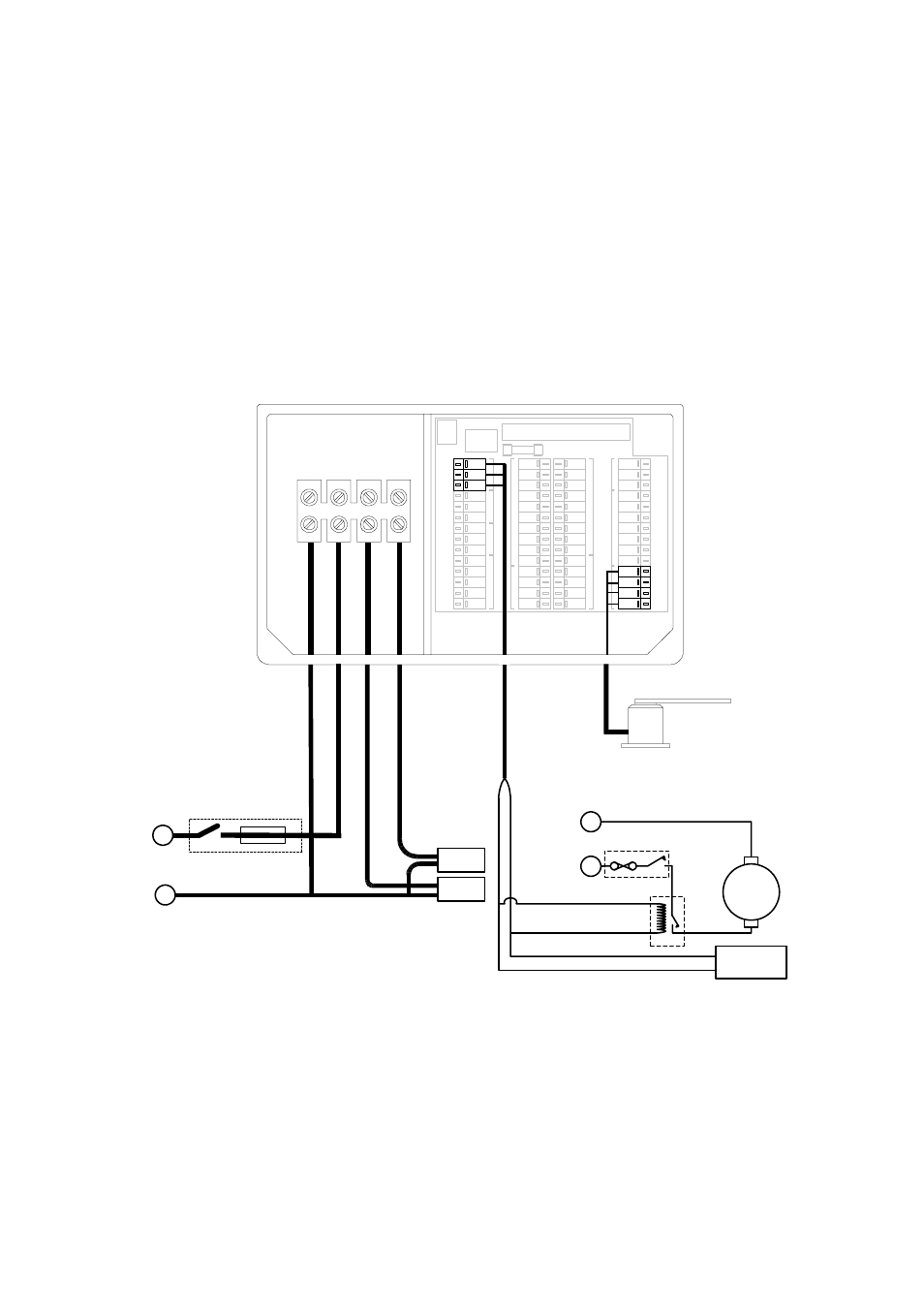
Continuous Drive Connections
These are general wiring instructions only, showing the
implementation of the ACP outputs to drive a continuous drive
pump solenoid valves. The continuous drive pump motor will also
require a heavy-duty supply, which is not provided. However,
suitable units can be obtained from your dealer. Clutch output is
used to control the motor supply.
Note:
The ram solenoid must be designed to operate at the
same voltage as the pump.
DRIVE
SUPPLY
DRIVE
SUPPLY
IN
OUT
-
+
-
1A
BR
BL
SLV
R
BL
SLV
BL
R
SLV
R
W
BR
G
V
BL
Y
BLK
SLV
R
G
SLV
BL
R
R
BL
SLV
G
W
Y
BR
R
BLK
SLV
R
G
BL
SLV
R
BL
SLV
R
BLK
G
W
BL
Y
SLV
BLK
G
R
SLV
CLUTCH
MOB
AL
ARM
PA
DDLE
G
Y
R
O
-S
T
A
B
IL
ISED
C
O
M
PASS
RUD
DER
J
O
YST
IC
K
HA
NDHE
LD
Rudder Reference Unit
RRF-ACP
Circuit Breaker
Heavy Duty
Power Supply
Bl
ack
Re
d
+
-
PORT
STBD
Continuous Drive
Pump Solenoid
Valves
Ram
Solenoid
Continuous
Running
Pump
Circuit Breaker*
Relay*
CR Pump
Supply
Bl
u
e
Brown
Clutch
Output
-
+
-
+
*Not supplied by B&G
Fig 4.7 Continuous Drive Connections