Store main parking stand, Monitor setup, Mvt monitor setup – Great Plains 1625AHL Operator Manual User Manual
Page 26: Pm400 monitor setup, Mvt monitor setup pm400 monitor setup
22
1625AH
Great Plains Manufacturing, Inc.
411-020M
2014-04-21
Store Main Parking Stand
Refer to Figure 8
13. Raise the 3-point hitch slightly.
14. Remove the lower pin
holding the parking
stand
. Swing the parking stand back and up until it
is above the rear hole
. Place the holding pin in the
rear hole and allow the parking stand to rest on it.
This is the transport position for the parking stand.
15. Adjust the top link of a 3-point long enough so the
ball swivel does not bottom out when fully raised.
16. Secure hoses using hose post loops (not shown) so
that hoses have ample slack for lifts and turns, but
cannot get caught in tongue lock or ball swivel.
Failure to do so could cause hose to be crushed
requiring hose replacement.
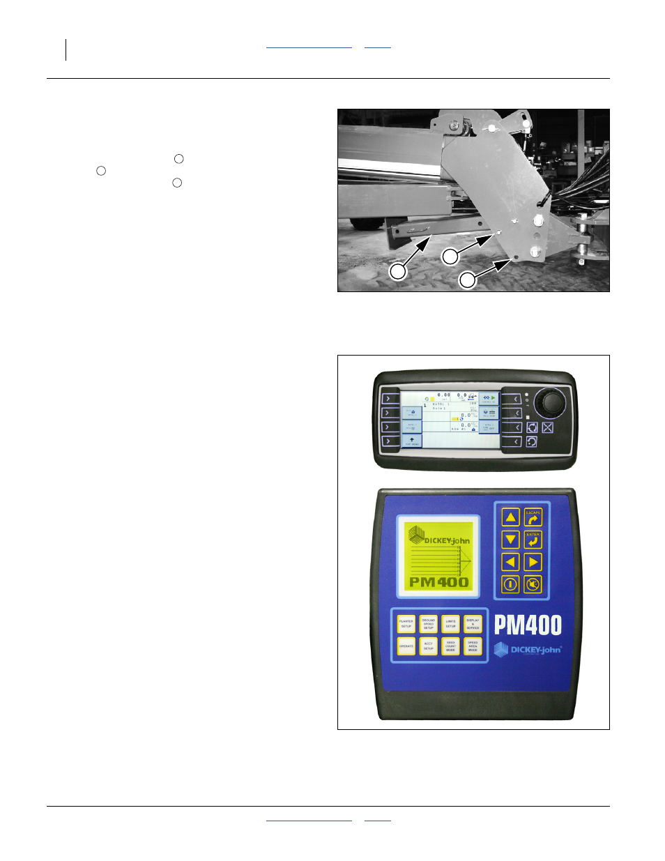
Monitor Setup
Refer to Figure 9
Model 1625AH planters include one of two
DICKEY-john
®
seed monitors, depending on row count
and fertilizer type:
• IntelliAg
®
MVT (Mini Virtual Terminal)
• PM400
Either systems monitors the following elements of a
1625AH planter:
• seeds at each row unit seed tube;
• ground speed;
• dry fertilizer at row drop tubes (1625AHD models);
and,
• dry fertilizer hopper level (1625AHD models).
MVT Monitor Setup
See “MVT Console Installation” on page 156.
Refer to the DICKEY-john
(11001-1643) for monitor operations, and the MVT Quick
Start Guide (11001-16
a
) for setup.
PM400 Monitor Setup
See “PM400 Console Installation” on page 156.
Refer to the DICKEY-john
®
PM400 Console Manual
(11001-1372) for monitor operations.
After installation, and prior to first field use, the monitor
must be setup with the row spacing and speed sensor
constant, as well as your preferences for information
display. Row count is auto-assigned, but any other
DICKEY-john
®
default values are not likely to be correct
for your planter.
Row spacing data may be found in the Appendix.
Figure 8
Storing Parking Stand
22813
5
6
7
5
7
6
Figure 9
PM400 and MVT Monitors
36211
36218