Install marker shear bolts, Install marker extension tube, Check disk orientation – Great Plains 1625AHL Operator Manual User Manual
Page 157
Great Plains Manufacturing, Inc.
Appendix B - Pre-Delivery
153
2014-04-21
411-020M
Heavy Overhead Object Hazard:
Use adequate lifting means. Use multiple attachment points.
Use extra personnel to control the load. The arm section may
weight up to 300 pounds (135 kg), and does not balance at the
center of its considerable length. if it falls, or you lose control
of the load, workers could suffer serious or fatal injuries.
20. Orient the arm (
or
) with the shear pin hole to
the rear (flat plate at the hinge end up, angled edge
of plate forward, and the center tube below).
Hoist the arm, resting the single-tube end in the
transport rest, and aligning the shear pivot tube with
the shear pivot holes in the hinge
.
Insert a shear pin
. Secure with second washer
and cotter
.
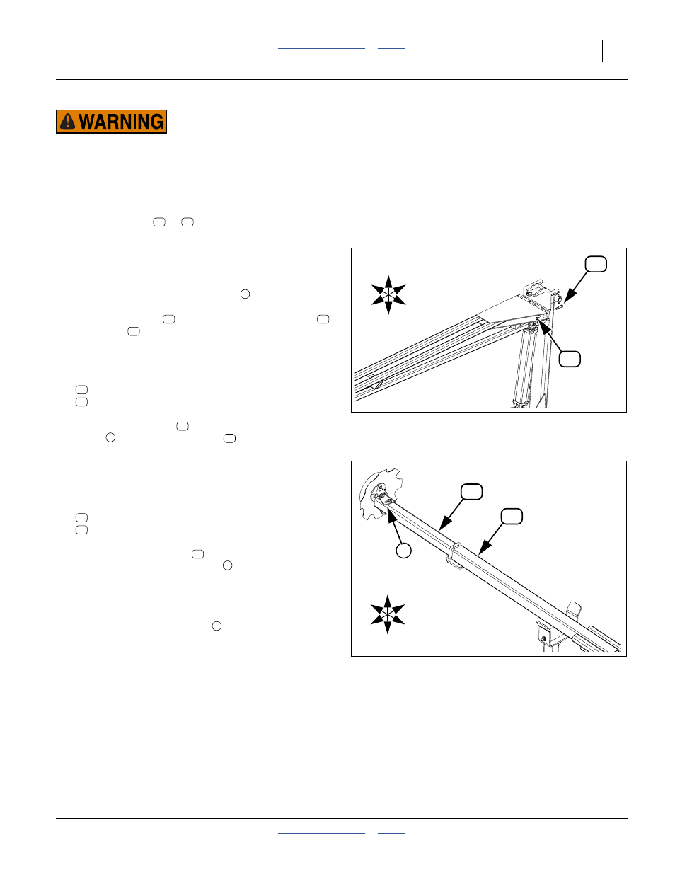
Install Marker Shear Bolts
Refer to Figure 127
21. Select one each:
802-130C HHCS 1/2-13X2 1/2 GR5
803-019C NUT LOCK 1/2-13 PLT
Insert the shear bolt
from the wing end of the
hinge
. Secure with lock nut
.
Install Marker Extension Tube
Check Disk Orientation
Refer to Figure 128 (C: to Center; W: to Wing)
22. Select one of:
113-794D MARKER EXTENSION TUBE
421-555D MARKER EXTENSION TUBE
These tube assemblies
are identical for LH and
RH use. The disk and spindle
are pre-assembled.
Prior to installing the marker extension tube, inspect
the disk assembly. The bolts securing the spindle
weldment to the tube are to be vertical after
installation, and the spindle
is to be to the front.
This is merely the factory default orientation. The
operator may change it as needed.
Figure 127
LH Marker Shear Bolt
24408
U
D
C
W
F
B
33
27
11
12
4
14
42
43
27
33
27
4
33
Figure 128
LH Marker Spindle Orientation
36261
11
5
U
D
F
B
W
C
13
13
13
13
5
5