Insert and secure tube, Press wheel installation – Great Plains 1625AHL Operator Manual User Manual
Page 158
154
1625AH
Great Plains Manufacturing, Inc.
411-020M
2014-04-21
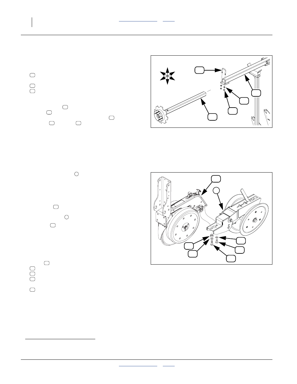
Insert and Secure Tube
For each wing:
Refer to Figure 129 (C: to Center; W: to Wing)
23. Select one:
806-110C U-BOLT 5/8-11 X 3 1/32 X 4 1/2
and two sets:
804-022C WASHER LOCK SPRING 5/8 PLT
803-021C NUT HEX 5/8-11 PLT
Minding the spindle orientation, insert the marker
extension tube
into the marker arm second
section
to a depth of about
a
18 inches (45 cm).
Secure the extension with the U-bolt
, lock
washers
and nuts
.
Press Wheel Installation
Refer to Figure 130
Press wheel assemblies
may be removed to meet
shipment clearance requirements. The removed
assemblies are found either in a crate, or a seed hopper.
Refer to Figure 131
There may be two types of press wheel assemblies:
• Long mount
assemblies, which are used on the
front (short) row of a twin pair. These mounts have a
series of notches
on the side.
• Mid mount
assemblies, which are used on the long
(rear) row of a twin pair. These mounts have smooth
sides.
Refer to Figure 130
For each row with press wheels dismounted:
24. Remove from the rear most two bolt holes of the
shank
and save one each:
405-032D 1X12 PW ADJUSTER
802-091C HHCS 1/2-13X1 1/2 GR5
802-258C HHCS 1/2-13X1 GR5
and two:
804-015C WASHER LOCK SPRING 1/2 PLT
a. Exact extension value depends on row spacing, row utilization and desired disk angle. Setting this requires full monitor and hydraulic
connections, then unfolding the planter and markers in field conditions. See “Marker Extension” on page 161.
Figure 129
LH Marker Extension Tube
24408
U
D
C
W
F
B
45
13
41
35
11
45
41
35
13
11
45
41
35
Figure 130
Press Wheel Installation
25383
20
6
21
40
26
40
29
6
18
7
19
20
21
26
29
40