Preparation and setup, Tramlining – Great Plains V-300F Predelivery Manual User Manual
Page 37
1/2/2006
148-057Q
35
Preparation and Setup
Preparation and Setup
Tramlining
All tramlines for this drill were set up on the fol-
lowing assumptions:
• 3 meter planting width with 19 openers
equally spaced at 15.8 cm.
• 1.8 meter wheel spacing of the tramlines.
With these assumptions, the feeder cup al-
lows for the tramline clutches to be placed on
rows 1, 4, 6, 13, 14, and 16. Two clutches are
assembled as standard on rows 4 and 16. An
additional clutch and jumper cable will be re-
quired on some patterns (ie 20 meter sprayer/
20 bouts).
The tramline clutch locations are as follows:
• 12 meter sprayer/4 bouts:
a.
Asymmetric right or left hand.
i.
Tramlines will be on rows 6 and
14.
b.
Symmetric.
i.
Tramlines will be on rows 4 and
16 (2nd bout must overlap 1st
bout 1/2 drill width).
• 15 meter sprayer/5 bouts:
a.
Symmetric.
i.
Tramlines will be on rows 4 and
16.
• 18 meter sprayer/6 bouts:
a.
Asymmetric right or left hand.
i.
Tramlines will be on rows 6 and
14.
b.
Symmetric.
i.
Tramlines will be on rows 4 and
16 (2nd bout must overlap 1st
bout 1/2 drill width).
• 20 meter sprayer/20 bouts
a.
Special Pattern:
i.
Tramlines will be on rows 1, 13,
and 14. (This pattern requires an
optional clutch and jumper cable,
which connects rows 1 and 13 to-
gether).
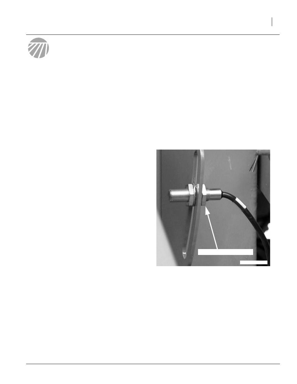
Refer to Figure 60
NOTE: On Tramline adjust screw to 1/8” of
magnet. Screw can also be adjusted up or
down in the slot. When drill is raised, the
sensor should be right on the magnet.
Otherwise, if sensor passes magnet it may
possibly read more than once.
On shaft monitors, adjust screw to 1/8” of
magnet. Screw will not adjust up or down.
Adjustment Screw
23387
Figure 60
Adjustment Screw