Tires and hub, Struts, Transport lock channel – Great Plains V-300F Predelivery Manual User Manual
Page 19
1/2/2006
148-057Q
17
Assembly
23302
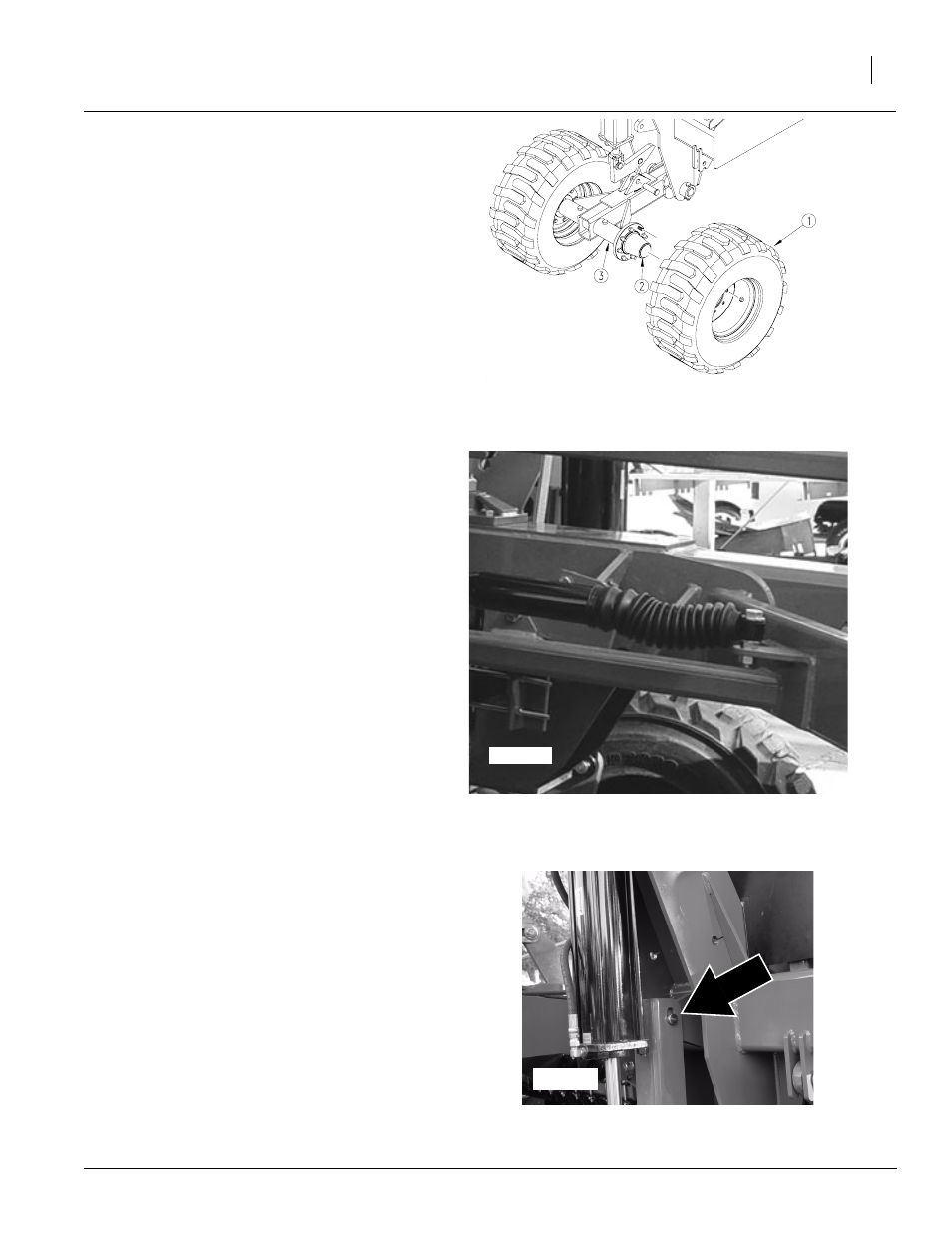
Figure 22
Gauge Wheel Tires and Hub
23308
Figure 23
Installing Struts
Tires and Hub
NOTE: Install tires as shown in Figure 22. For
each gauge wheel arm, tires come in a pair of
left and right. To distinguish left and right tires,
the side with the valve stem should be out
away from the gauge wheel arm and the tire
tread should be pointing the same direction
as shown in Figure 22.
Refer to Figure 22
1.
Attach inside and outside hub (2) to
gauge wheel arm (3) using 3/4-10 x 5
bolts and 3/4-10 hex lock nuts.
2.
Secure inside gauge wheel tire to inside
hub assembly with bolts and lug nuts.
3.
Secure outside gauge wheel tire (1) to
outside hub assembly (2) with bolts and
5/8-18 x 90 lug nuts.
4.
Repeat steps 1 - 3 for the opposite gauge
wheel.
Struts
Refer to Figure 23
1.
Remove shipping wire securing strut to
frame.
2.
Swing strut toward the box. If necessary,
loosen bolt attaching strut to frame.
3.
Attach strut to the box with 5/8-11 x 3
bolt, two 5/8 flat washers, 5/8-11hex nut
jam, and 5/8-11 lock nut.
4.
Tighten all bolts.
5.
Repeat steps 5-8 for opposite strut.
Transport Lock Channel
Refer to Figure 24
NOTE: After struts are installed, it is neces-
sary to lift the box with forklift or other imple-
ment so that the transport lock channels may
be installed. It may be necessary to remove
hydraulic plugs to expand cylinder.
6.
Align the slotted hole in the transport lock
channel with the hole in the frame and in-
sert cotter pin.
7.
Repeat on other side of drill.
22604
Figure 24
Installing Transport Lock Channel