Top link, Contact wheel spring – Great Plains V-300F Predelivery Manual User Manual
Page 20
V300, V300F
148-057Q
1/2/2006
18
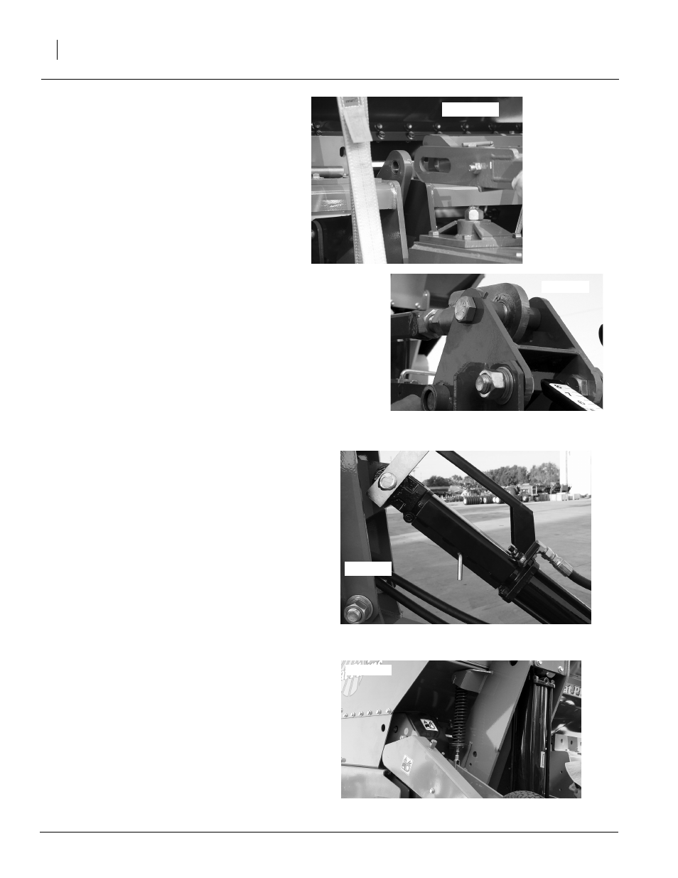
Figure 26
Top Link Level Hydraulic Cylinder with Cylinder Lock
Top Link
Refer to Figure 25
1.
Attach top link to level link rocker arm wldmt
on box using 1 1/4 x 3 clevis pin, 1 1/4 flat
washers, and 1/4 x 2 cotter pin.
2.
Secure other end of top link to level link pivot
lever with 1-8 x 7 bolt, spacer tube, 1 flat
washer, and 1-8 hex nut.
NOTE: The starting point for adjusting the top link
is 103 inches from center of level link adjuster to
center of level link arm weldment.
Refer to Figure 26
3.
Attach top link level hydraulic cylinder to
frame and tongue. If necessary, remove hy-
draulic plugs to expand cylinder.
4.
Lock cylinder in place using pin and transport
cylinder lock.
5.
Secure 96’ hose to rod end of top link level hy-
draulic cylinder using elbow fitting.
6.
Attach other 96’ hose to base end of top link
level hydraulic cylinder using elbow fitting.
Contact Wheel Spring
Refer to Figure 27
1.
Remove shipping wire securing contact
wheel to box. Carefully lower contact wheel.
NOTE: Pins securing spring need to be inserted
from the inside out.
2.
Attach spring to box on one side of contact
wheel using pins.
3.
Using pins, secure spring to contact wheel
arm.
4.
Repeat process on other side of contact
wheel.
23309
23323
Figure 25
Attaching Top Link
23311
23324
Figure 27
Contact Wheel Spring