Press wheel – Great Plains V-300F Predelivery Manual User Manual
Page 22
V300, V300F
148-057Q
1/2/2006
20
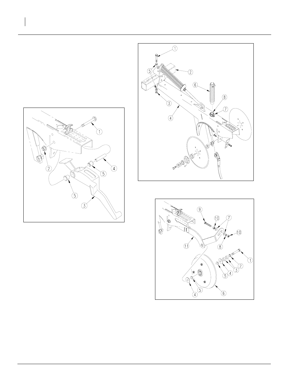
Refer to Figure 32
NOTE: For shipping purposes, the two end openers
were removed from the subframe. They will need to
be reinstalled according to steps 3 and 4 below.
3.
Attach the two end openers (4) to the opener
subframe (2) - one on each end of the subframe
(2). Secure openers (4) to subframe (2) using
bolts (1), washers (5), and lock nuts (3).
4.
Connect seed hose (6) to seed tube opener (8)
securing with hose clamp (7).
Figure 33
Attach Press Wheel Arm to Opener
Figure 32
Attach Opener to Subframe
23353
23358
Figure 34
Cast Press Wheel
23354
Press Wheel
Refer to Figure 33
NOTE: The press wheel arm weldment will need to be
installed on the two end openers. Install as shown in
Figure 33.
1.
Attach press wheel arm weldment to opener using
bolt (1), parallel arm pivot bushings (5), press
wheel pivot tube (4), and hex lock nut (2).
Refer to Figure 34
NOTE: Each type of press wheel installs differently. If
installing 2” x 13” or 3” x 13” single press wheel, com-
plete only step 2.
If installing cast press wheel, complete both steps 2
and 3.
For all press wheel types:
2.
Attach press wheel (6) to press wheel arm weld-
ment (11). Secure press wheel (6) to weldment us-
ing bolt (1), lock washers (2), spacer bushings (3),
and washers (4 and 5).
For cast press wheel assembly only:
3.
Once the press wheel (6) is attached to the press
wheel arm weldment (11), attach bolt (9), hex
nuts (10), flat washers (7), and lock washer (8) to
press wheel arm weldment.