Powers 595 Series 11 Self-Operating Temperature Regulators - Type WM 3-Way Water Mix User Manual
Page 8
8
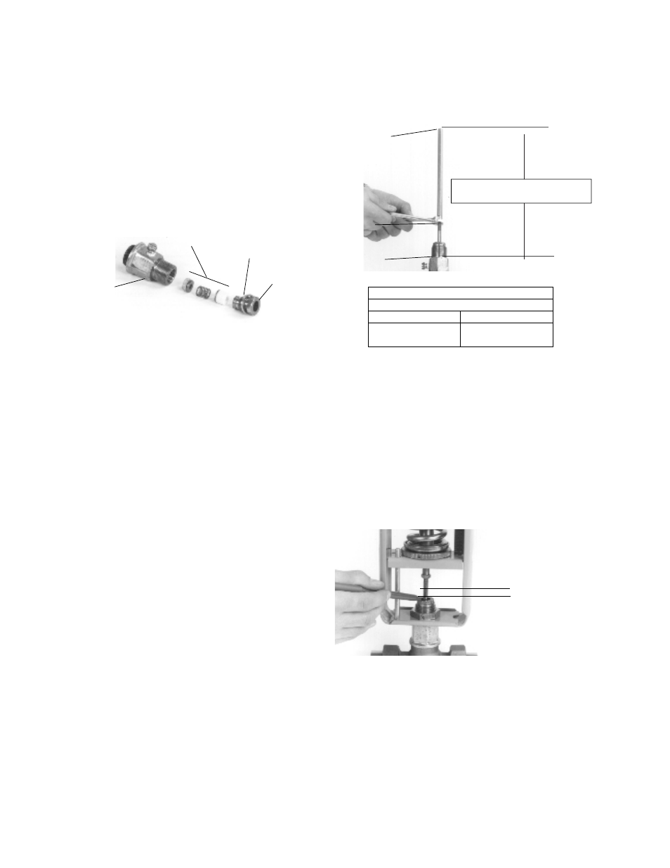
17. With stem in full UP position (the valve plug firmly seated),
screw stem extension [4] to the dimension shown in Figure 14
and tighten into place with hex nut [12].
18. Make sure the valve stem is in the full up position when replac-
ing the spring seat and piston plate assembly on the large
valves.
19. Assemble the remaining parts in reverse order.
TESTING THE THERMAL SYSTEM
1.
Stop the flow of fluid through the line.
2.
Raise the temperature of the bulb above the set point temper-
ature by placing it in a container of hot water. This will cause
the plug to fully seat.
3.
Figure 15. With the valve plug seated in the bottom port "B,"
use a felt tip pen to mark the position of the packing gland
assembly on the stem.
4.
Place the bulb in a pan of cool water. Cool the bulb 30°F
(16°C) below set point so the valve is fully open.
5.
With the valve plug now seated on the upper port “U,” use the
pen to mark the new position of the packing gland assembly
on the stem.
To replace packing
Follow To fully disassemble regulator from valve steps 1-6.
6.
Figure 11. Use a 5/16" wrench on the flats of the stem exten-
sion [4] and a 7/16" wrench on the hex nut [12] to loosen and
remove them.
7.
Use the 1-3/8" wrench to loosen and remove bonnet [20].
8.
Carefully pull out stem assembly [30]. Check the stem. It must
have a polished surface that is free of roughness and pitting.
Replace any parts if necessary.
9.
Figure 13. Remove packing gland [14], and all packing com-
ponents [15a-15e].
10. Clean packing chamber, taking care not to scratch seating
surfaces. Be sure chamber is free of dirt and grease.
11. For 1" - 2" valves, place the upper gasket [21] on body before
the bonnet.
12. Replace bonnet [20] and stem [30] into valve body.
NOTE: You must replace the bonnet and stem before attempt-
ing to insert the packing. Otherwise, you may tear the packing
rings.
13. For standard packing kits, install the parts as shown in Figure
13.
Slide part(s) [15e], followed by [15d] and [15c] over the stem.
Gently push them into the packing chamber.
NOTE: Some kits do not include all the listed packing parts
(see page 12), but the order for part installation is the same.
14. For EP V-rings, lubricate the rings first.
Slide each V-ring [15b] over the stem and carefully push it into
the packing chamber.
15. Place the packing gland spacer [15a] on top of the bonnet.
16. Thread the packing gland assembly [14] into the bonnet.
Tighten the gland assembly against the spacer.
Stem Setting Dimension (See Above)
Valve Size
1/2" to 2"
2-1/2" to 4"
10-1/16" (+1/32, -0)
8-3/16" (+1/32, -0)
[256mm (+.79, -0)]
[208mm (+.79, -0)]
13. PACKING COMPONENTS
Packing Kit
(15a-e)
Packing Gland
Spacer
Packing
Gland
Bonnet
Hex Nut
Top of Stem
Extension
Top of
Bonnet
SEE CHART BELOW
14. STEM EXTENSION REASSEMBLY DIMENSION
Distance between
two marks = Valve
Travel
15. VALVE TRAVEL MEASUREMENT