Product identification – Powers 595 Series 11 Self-Operating Temperature Regulators - Type WM 3-Way Water Mix User Manual
Page 5
5
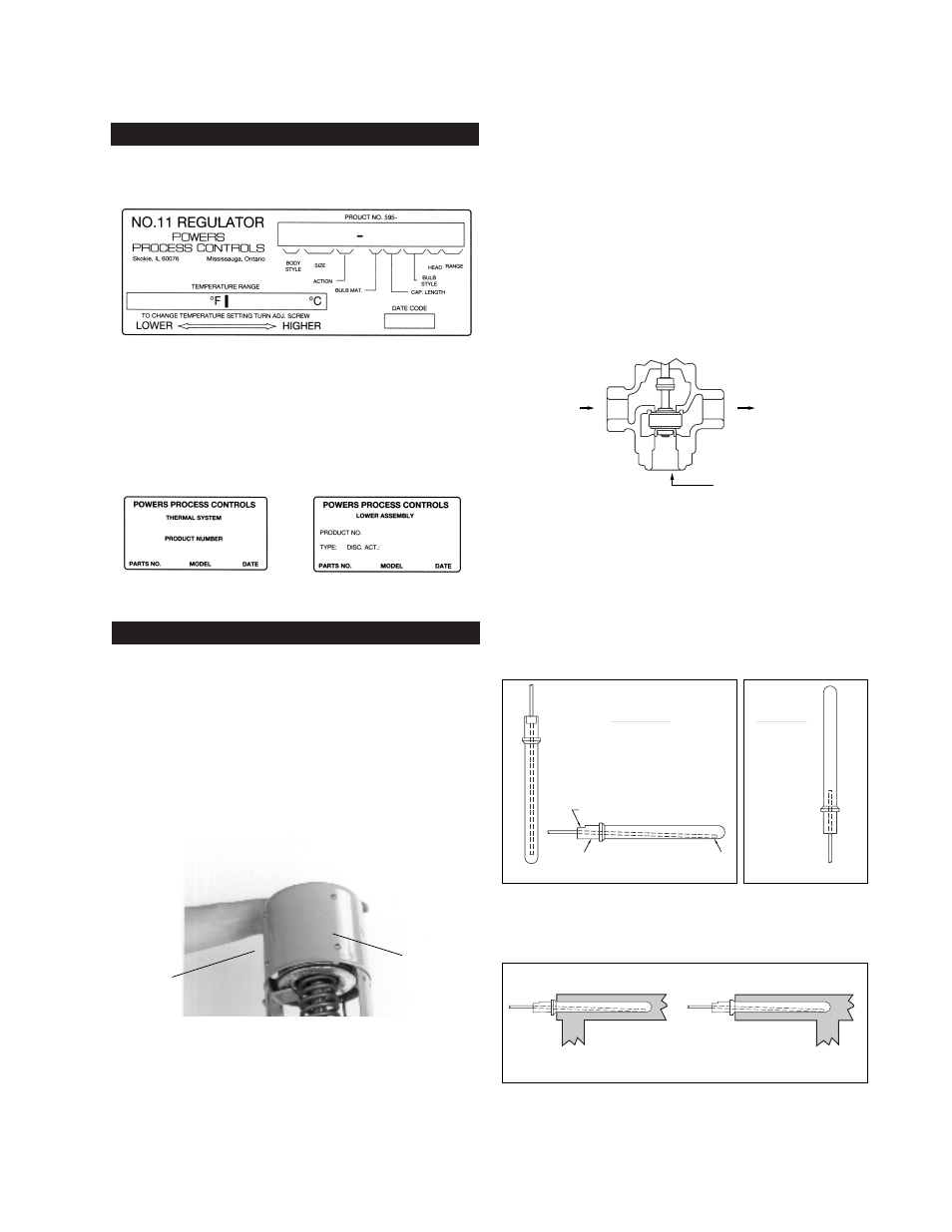
PRODUCT IDENTIFICATION
A red label should be on the front face of the thermal system.
Figure 1. This label contains information required to properly main-
tain, service and order parts for this product. If there is no label,
look for a white label on the inside of the thermal system legs
(Figure 2A) or the valve body vertical yoke (Figure 2B). When
replacing the original thermal assembly or valve body, secure the
old red label onto the valve or thermal system or ink the number
onto the body.
INSTALLATION
TOOLS NEEDED
• Straight slot screwdriver
• 5/16" open end wrench
• 3/8" open end wrench
• 7/16" open end wrench
• 1-3/8" open end wrench
• Pliers
• 1/2" wrench for hi-power regulator housing bolts
BEFORE INSTALLING VALVE
1.
Figure 3. For 2-1/2” to 4” valves, remove bellows stops
before installation and use.
2.
To insure proper system operation, thoroughly flush all piping
and valves to rid them of all scale, dirt and debris.
Position Valve
3.
Select valve location with sufficient clearance to allow mainte-
nance. Install valve in line. The direction of the arrows on the
valve body must match the direction of the water or steam
flow.
For best results, we recommend installing the valve in a hori-
zontal line, and in the upright position with bellows head
above valve. The valve may also be installed in any position
within 90° of upright.
4.
Figure 4. The direction of the arrows on the valve body must
match the direction of the water flow.
Pipe the hot water to the bottom ‘B’ port, and the cold water
to the upper ‘U’ port. The mixed water will exit the valve
through the common ‘C’ port.
DO NOT reverse the inlets; the valve will not properly control
the temperature of the mixed water if hot and cold supplies
are reversed.
INSTALL BULB
5.
Figure 5a shows proper bulb orientation. Figure 5b shows the
special bulb needed for upwards vertical positioning.
6.
Figure 6. For any position, fully immerse the bulb in the flow of
the medium.
These instructions are for D style bulbs - for installation of other
styles, refer to tag attached to bulb.
Correct: Bulb in flow of medium
Incorrect: Bulb not in flow of medium
U
C
B
Hot Water Inlet
Tempered Water Outlet
Cold Water Inlet
1. PRODUCT LABEL
2B. VALVE BODY LABEL
2A. THERMAL SYSTEM LABEL
3. BELLOWS STOPS
Bellows
Stop
Bellows
Stop
Removed
4. INLET PIPING
WORD "TOP" ON FLAT SURFACE FACING UP
HEAD
END
TOP
Standard Bulb
Downward Vertical (left)
or
Horizontal (below)
Only
Special Bulb
Upward Vertical
Only (right)
5B. SPECIAL BULB
5A. BULB ORIENTATION
6. BULB POSITION